
FTR-C2 Series
ULTRA MINIATURE RELAY
SIGNAL RELAY
n
FEATURES
l
Dimensions of large contact gap relay
Height:
.8 mm maximum (THT)
2 mm maximum (SMT)
Length:
20.2 mm maximum
Width:
0 mm maximum
l
Conforms to IEC60950 / EN60950 / UL950/ CSA C22.2
No.950 spacing & high breakdown voltage
l
Recognized by UL/CSA and Bsi
UL: File E6365 Vol. 2 Sec.4
CSA:Mastercontract169663Certificate1088921
Clearance:
2.0 mm (between open contacts,
coil and contacts, contact sets)
Creepage:
2.0 mm (between open contacts,
coil and contacts, contact sets)
l
HIGH RELIABILITY
Bifurcated contacts
l
Low power consumption 300 mV
l
RoHS Compliant since production
n
ORDERING INFORMATION
FTR-C2 C A 02 G -B 05*
[Example]
(a) (b) (c) (d) (e) (f) (g)
Remarks: Actual marking on relay would not carry code FTR and be as below:
Ordering code
Actual marking
FTR-C2CA03G
C2CA03G
*only SMT version
RoHS compliant
)
a
(
e
m
a
N
s
e
ir
e
S
2
C
-
R
T
F
)
b
(
e
c
n
a
r
a
e
r
p
p
A
l
n
a
i
m
r
e
T
e
p
y
t
e
l
o
h
h
g
u
o
r
h
T
:
C
e
p
y
t
t
n
u
o
m
e
c
a
fr
u
S
:
G
)
c
(
n
o
it
c
n
u
F
n
o
it
a
r
e
p
O
e
p
y
t
d
r
a
d
n
a
t
S
:
A
e
p
y
t
g
n
i
h
c
t
a
L
:
B
)
d
(
r
e
b
m
u
N
li
o
C
e
g
a
tl
o
V
l
a
n
i
m
o
N
)
e
(
l
a
ir
e
t
a
M
t
c
a
t
n
o
C
y
o
ll
a
r
e
v
li
S
:
G
)f
(
n
o
it
c
e
ri
d
g
n
i
s
o
l
c
n
e
y
a
l
e
R
n
o
it
c
e
ri
d
g
n
i
s
o
l
c
n
e
d
r
a
d
n
a
t
s
:
B
)
g
(
l
e
e
r
r
e
p
s
y
a
l
e
r
f
o
r
e
b
m
u
N
)
d
r
a
d
n
a
t
s
(
0
0
5
:
5
0

FTR-C2 Series
2
n
COIL DATA CHART
Standard type
Note:Allvaluesinthetablearemeasuredat20∞C.
Single coil latching type
l
e
d
o
M
l
a
n
i
m
o
N
e
g
a
tl
o
V
li
o
C
e
c
n
a
t
s
i
s
e
R
)
%
0
1
±
(
e
t
a
r
e
p
O
t
s
u
M
e
g
a
tl
o
V
e
s
a
e
l
e
R
t
s
u
M
e
g
a
tl
o
V
l
a
n
i
m
o
N
g
n
it
a
r
e
p
O
r
e
w
o
P
)
%
0
1
±
(
G
3
0
0
A
)
(
2
C
-
R
T
F
C
D
V
3
0
.
0
3
C
D
V
5
2
.
2
C
D
V
3
.
0
W
m
0
0
3
G
5
0
0
A
)
(
2
C
-
R
T
F
C
D
V
5
3
.
3
8
C
D
V
5
7
.
3
C
D
V
5
.
0
W
m
0
0
3
G
2
1
0
A
)
(
2
C
-
R
T
F
C
D
V
2
1
0
.
0
8
4
C
D
V
0
0
.
9
C
D
V
2
.
1
W
m
0
0
3
G
4
2
0
A
)
(
2
C
-
R
T
F
C
D
V
4
2
0
.
0
2
9
,
1
C
D
V
0
0
.
8
1
C
D
V
4
.
2
W
m
0
0
3
l
e
d
o
M
l
a
n
i
m
o
N
e
g
a
tl
o
V
li
o
C
e
c
n
a
t
s
i
s
e
R
)
%
0
1
±
(
e
g
a
tl
o
V
t
e
S
e
g
a
tl
o
V
t
e
s
e
R
l
a
n
i
m
o
N
g
n
it
a
r
e
p
O
r
e
w
o
P
)
%
0
1
±
(
G
3
0
0
B
)
(
2
C
-
R
T
F
C
D
V
3
0
.
0
6
C
D
V
5
2
.
2
C
D
V
5
2
.
2
W
m
0
5
1
G
5
0
0
B
)
(
2
C
-
R
T
F
C
D
V
5
0
.
7
6
1
C
D
V
5
7
.
3
C
D
V
5
7
.
3
W
m
0
5
1
G
2
1
0
0
B
)
(
2
C
-
R
T
F
C
D
V
2
1
0
.
0
6
9
C
D
V
0
0
.
9
C
D
V
0
0
.
9
W
m
0
5
1
G
4
2
0
B
)
(
2
C
-
R
T
F
C
D
V
4
2
0
.
0
4
8
,
3
C
D
V
0
0
.
8
1
C
D
V
0
0
.
8
1
W
m
0
5
1
FTR-C2 Series
3
n
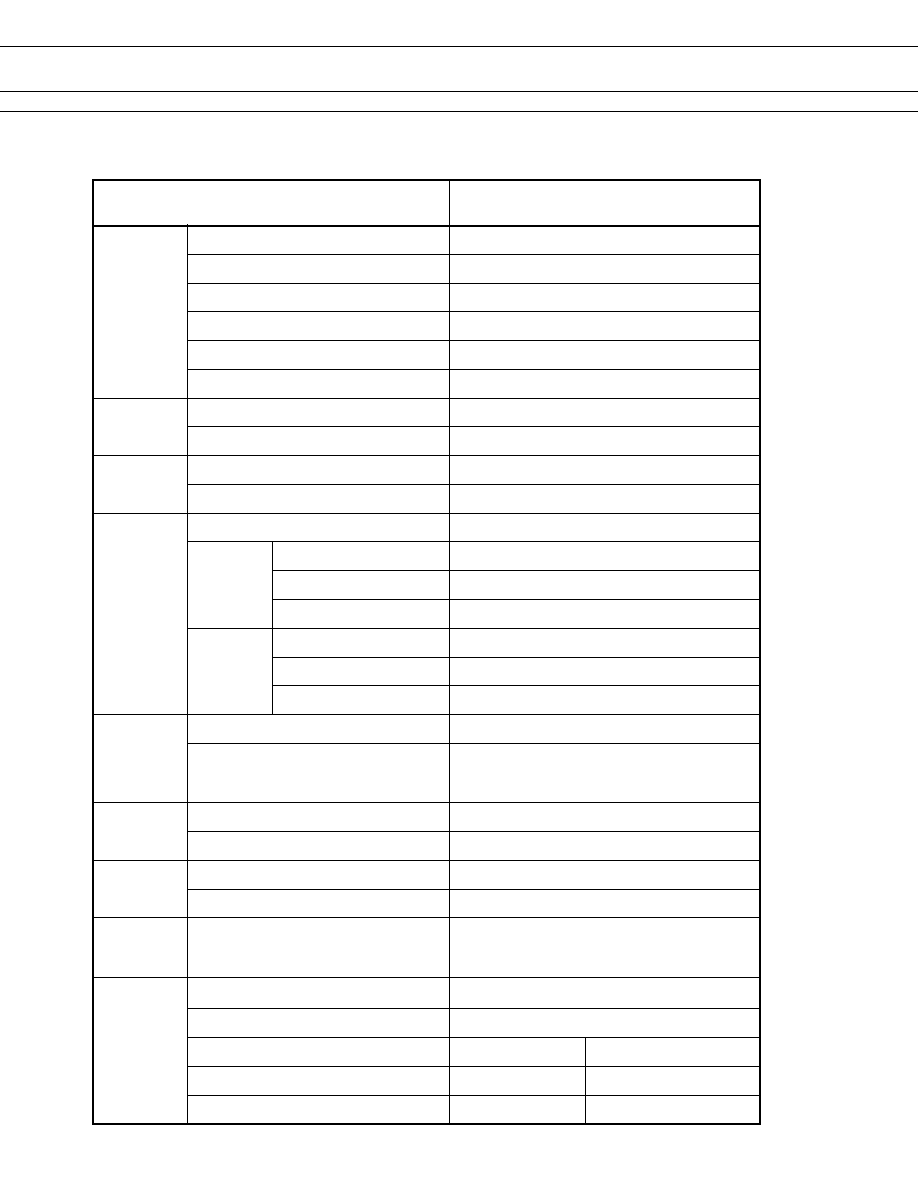
SPECIFICATIONS
m
e
tI
G
)
(
A
C
2
C
-
R
T
F
G
)
(
-
A
G
2
C
-
R
T
F
t
c
a
t
n
o
C
t
n
e
m
e
g
n
a
r
r
A
C
m
r
o
F
2
l
a
ir
e
t
a
M
y
o
ll
a
r
e
v
li
S
)l
a
it
i
n
i(
e
c
n
a
t
s
i
s
e
R
)
C
D
V
6
A
1
t
a
(
m
h
o
m
0
5
1
.
x
a
M
r
e
w
o
P
g
n
i
h
c
ti
w
S
.
x
a
M
W
0
3
/
V
A
5
.
7
3
e
g
a
tl
o
V
g
n
i
h
c
ti
w
S
.
x
a
M
C
D
V
0
2
2
,
C
A
V
0
5
2
t
n
e
r
r
u
C
g
n
i
h
c
ti
w
S
.
x
a
M
A
1
li
o
C
e
r
u
t
a
r
e
p
m
e
T
g
n
it
a
r
e
p
O
)t
s
o
rf
o
n
(
C
∞
5
8
+
o
t
C
∞
0
4
-
e
g
a
tl
o
V
e
l
b
a
w
o
ll
A
.
x
a
M
)
C
∞
0
2
t
a
(
e
g
a
tl
o
v
l
a
n
i
m
o
n
%
0
5
1
e
u
l
a
V
e
m
i
T
e
m
i
T
e
t
a
r
e
p
O
e
c
n
u
o
b
t
u
o
h
ti
w
,
e
g
a
tl
o
v
l
a
n
i
m
o
n
t
a
(
s
m
5
1
.
x
a
M
)
e
d
o
i
d
t
u
o
h
ti
w
(
e
m
i
T
e
s
a
e
l
e
R
e
c
n
u
o
b
t
u
o
h
ti
w
,
e
g
a
tl
o
v
l
a
n
i
m
o
n
t
a
(
s
m
5
1
.
x
a
M
n
o
it
a
l
u
s
n
I
)
C
D
V
0
0
5
t
a
(
e
c
n
a
t
s
i
s
e
R
m
h
o
M
0
0
0
,
1
.
n
i
M
c
ir
t
c
e
l
e
e
i
D
t
h
g
n
e
rt
S
s
t
c
a
t
n
o
c
n
e
p
o
n
e
e
w
t
e
B
e
t
u
n
i
m
1
,
C
A
V
0
0
5
,
1
s
t
c
a
t
n
o
c
t
n
e
c
a
j
d
a
n
e
e
w
t
e
B
e
t
u
n
i
m
1
,
C
A
V
0
0
5
,
1
s
t
c
a
t
n
o
c
d
n
a
li
o
c
n
e
e
w
t
e
B
e
t
u
n
i
m
1
,
C
A
V
0
0
0
,
2
e
g
r
u
S
h
t
g
n
e
rt
S
s
t
c
a
t
n
o
c
n
e
p
o
n
e
e
w
t
e
B
)
s
o
r
c
i
m
0
0
7
/
0
1
t
a
(
V
0
0
5
,
2
s
t
c
a
t
n
o
c
t
n
e
c
a
j
d
a
n
e
e
w
t
e
B
)
s
o
r
c
i
m
0
0
7
/
0
1
t
a
(
V
0
0
5
,
2
s
t
c
a
t
n
o
c
d
n
a
li
o
c
n
e
e
w
t
e
B
)
s
o
r
c
i
m
0
0
7
/
0
1
t
a
(
V
0
0
5
,
2
e
fi
L
l
a
c
i
n
a
h
c
e
M
0
1
x
0
1
6
)
z
H
0
1
t
a
(
.
n
i
m
s
n
o
it
a
r
e
p
o
)
d
a
o
l
e
v
it
s
i
s
e
r
(
l
a
c
ir
t
c
e
l
E
0
1
x
0
0
1
3
z
H
5
.
0
,
C
D
V
0
3
,
A
1
t
a
.
n
i
m
s
n
o
it
a
r
e
p
o
0
1
x
0
0
1
3
z
H
5
.
0
,
C
D
V
8
4
,
A
1
.
0
t
a
.
n
i
m
s
n
o
it
a
r
e
p
o
0
1
x
0
0
1
3
z
H
5
.
0
,
C
D
V
5
2
1
,
A
3
.
0
t
a
.
n
i
m
s
n
o
it
a
r
e
p
o
n
o
it
a
r
b
i
V
e
c
n
a
t
s
i
s
e
R
n
o
it
a
r
e
p
o
s
i
M
m
m
3
.
3
f
o
e
d
u
ti
l
p
m
a
e
l
b
u
o
d
t
a
z
H
5
5
o
t
0
1
e
c
n
a
r
u
d
n
E
m
m
5
f
o
e
d
u
ti
l
p
m
a
e
l
b
u
o
d
t
a
z
H
5
5
o
t
0
1
k
c
o
h
S
e
c
n
a
t
s
i
s
e
R
n
o
it
a
r
e
p
o
s
i
M
s
/
m
0
0
3
.
n
i
M
2
e
c
n
a
r
u
d
n
E
s
/
m
0
0
0
,
1
.
n
i
M
2
A
S
C
/
L
U
g
n
it
a
R
t
c
a
t
n
o
C
C
A
V
5
2
1
A
3
.
0
C
D
V
0
3
A
1
C
D
V
0
1
1
3
.
0
0
5
9
0
6
0
C
E
I
0
5
9
1
L
U
2
.
2
2
C
0
5
9
.
o
N
0
5
9
0
6
N
E
s
s
a
l
C
n
o
it
a
l
u
s
n
I
n
o
it
a
l
u
s
n
I
y
r
a
t
n
e
m
e
l
p
p
u
S
e
g
a
tl
o
V
g
n
i
k
r
o
W
V
0
5
2
e
e
r
g
e
D
n
o
it
u
ll
o
P
)
e
d
i
s
t
u
o
(
2
)
e
d
i
s
n
i(
1
e
c
n
a
r
a
e
l
C
)
e
d
i
s
t
u
o
(
m
m
0
.
2
)
e
d
i
s
n
i(
m
m
0
.
2
e
c
n
a
t
s
i
D
e
g
a
p
e
e
r
C
)
e
d
i
s
t
u
o
(
m
m
5
.
2
)
e
d
i
s
n
i(
m
m
0
.
2

FTR-C2 Series
4
n
DIMENSIONS AND SCHEMATICS
Through hole type
(Bottom view de-energized position)
5.08 ±0.3
5.08 ±0.3
7.62 ±0.3
(1.135)
(1.115) 7.62 ±0.3
1
1.4 ±0.3
3.5
n
TERMINAL DESIGNATIONS
n
RECOMMENDED MOUNTING PAD
Unit: mm
Unit: mm
5.08 ±0.1
7.62 ±0.1
(1.135)
5.08 ±0.1
7.62 ±0.1
(1.1
15)
8-O 0.9±0.1
Polarity bar
Polarity bar
S R
S: shows polarity of set position
R: shows polarity of reset position
(Bottom view reset position)
Single Coil Latching Type

FTR-C2 Series
5
n
DIMENSIONS AND SCHEMATICS
Surface mount type
5.08 ±0.3
7.62 ±0.3
(1.135)
5.08 ±0.3
1
1.7 ±0.3
1.5
10.8 ±0.3
7.62 ±0.3
0.25
+.03
3
o
±.2
o
0.3
+0 -0.1
(Top view de-energized position)
n
TERMINAL DESIGNATIONS
n
RECOMMENDED MOUNTING
Unit: mm
Unit: mm
5.08 ±0.1
5.08 ±0.1
7.62 ±0.1
3±0.1
3±0.1
8.9±0.1
1 ±0.1
1 ±0.1
1 ±0.1
1 ±0.1
Polarity bar
S: shows polarity of set position
R: shows polarity of reset position
S R
Polarity bar
(Top view reset position)
Single Coil Latching Type

FTR-C2 Series
6
n
RECOMMENDED SOLDERING CONDITIONS
(TEMPERATURE PROFILE)
Note: 1.Temperatureprofilesshowthetempera-
ture of PC board surface.
2. Please perform soldering test with your
actual PC board before mass produc-
tion, since the temperatures of PC
board surfaces vary according to the
size of PC board, status of parts
mounting and heating method.
IRS (Infrared Reflow Soldering)
T
3
T
2
T
1
T
3
= 245C max.
T
2
= 200C max.
T
1
= 165C max.
0
T
emperature (C)
soldering
preheating
cooling
120 sec maximum 30 sec
Max.

FTR-C2 Series
RoHS Compliance and Lead Free Relay Information
Reflow Solder condtion for SMT
3. Moisture Sensitivity
l
Moisture Sensitivity Level standard is not applicable to electromechanical realys.
4. Tin Whisker
l
SnAgCu and SnCuNi solder is known as low risk of tin whisker. No considerable length whisker was found
by our in-house test.
Wehighlyrecommendthatyouconfirmyouractualsolderconditions
Flow Solder condtion:
Pre-heating:
maximum120∞C
Soldering:
dip within 5 sec. at
260∞Csolerbath
Solder by Soldering Iron:
Soldering Iron
Temperature: maximum360∞C
Duration:
maximum 3 sec.
1. General Information
l
Relaysproducedafterthespecificdatecodethatisindicatedoneachdatasheetarelead-free
now. Most of our signal and power relays are lead-free. Please refer to Lead-Free Status Info.
(http://www.fujitsu.com/us/downloads/MICRO/fcai/relays/lead-free-letter.pdf)
l
Lead free solder paste currently used in relays is Sn-3.0Ag-0.5Cu.
l
All signal and most power relays also comply with RoHS. Please refer to individual data
sheets. Relays that are RoHS compliant do not contain the 5 hazardous materials that
are restricted by RoHS directive (lead, mercury, chromium IV, PBB, PBDE).
l
Ithasbeenverifiedthatusinglead-freerelaysinleadedassemblyprocesswillnotcauseany
problems (compatible).
l
"LF" is marked on each outer and inner carton. (No marking on individual relays).
l
Toavoidleadedrelays(forlead-freesample,etc.)pleaseconsultwithareasalesoffice.
l
We will ship leaded relays as long as the leaded relay inventory exists.
Note: Cadmium was exempted from RoHS on October 2, 2005. (Amendment to Directive 2002/95/EC)
2. Recommended Lead Free Solder Profile
l
Recommended solder paste Sn-3.0Ag-0.5Cu amd Sm-3.0 Cu-Ni (only FTR-B3 and FTR-B4 from
February 2005.
max. 20 sec.
90~20 sec.
20~30 sec.
(duration)
Cooling
Pre-heating
Soldering
Peak Temp.: max. 250C
250
220
30
30
0
T
e
m
p
e
r
a
t
u
r
e
(
C
)

FTR-C2 Series
8
Japan
Fujitsu Component Limited
Gotanda-Chuo Building
3-5, Higashigotanda 2-chome, Shinagawa-ku
Tokyo 4, Japan
Tel: (8-3) 5449-00
Fax: (8-3) 5449-2626
Email: promothq@ft.ed.fujitsu.com
Web: www.fcl.fujitsu.com
North and South America
Fujitsu Components America, Inc.
250 E. Caribbean Drive
Sunnyvale, CA 94089 U.S.A.
Tel: (-408) 45-4900
Fax: (-408) 45-490
Email: marcom@fcai.fujitsu.com
Web: http://www.fujitsu.com/us/services/edevices/components/
Europe
Fujitsu Components Europe B.V.
Diamantlaan 25
232 WV Hoofddorp
Netherlands
Tel: (3-23) 556090
Fax: (3-23) 5560950
Email: info@fceu.fujitsu.com
Web: http://www.fujitsu.com/emea/services/components/
Asia Pacific
Fujitsu Components Asia Ltd.
02E Pasir Panjang Road
#04-0 Citilink Warehouse Complex
Singapore 8529
Tel: (65) 635-8560
Fax: (65) 623-302
Email: fcal@fcal.fujitsu.com
Web: http://www.fujitsu.com/sg/services/micro/components/
Fujitsu Components International Headquarter Offices
©2005 Fujitsu Components America, Inc. All rights reserved. All trademarks or registered trademarks are the property off their respective
owners.
Fujitsu Components America does not warrant that the content of datasheet is error free. In a continuing effort to improve our products Fujitsu
ComponentsAmerica,Inc.reservestherighttochangespecifications/datasheetswithoutpriornotice.Rev.11/18/2005.