
FTR-F4 SERIES
n
FEATURES
l
Small high density type relay 288mm
2
save 24% compared
to VB
l
UL/CSA TV-3 rating
l
Insulation distance: minimum 6 mm between coil and con-
tacts (IEC65)
Dielectric strength: 4 KVAV
Surge strength: 0 KV
l
Card separation system for high noise resistance between
coil and contacts
l
UL 94V-0 flamability materials, UL Class B (130∞C)
l
Safety standards
UL, CSA, VDE, SEMKO pending
l
RoHS compliant since date code: 0437L2
Please see page 5 for more information
n
APPLICATIONS
l
CRT monitor EMI protection
l
Audio system speaker protection
FTR-F4 Series
POWER RELAY
2 POLE 5A/TV-3 RATED COMPACT TYPE
(a)
Series Name
FTR-F4 : FTR-F4 Series
(b)
Contact Arrangement
A
: 2 form A (DPST)
(c)
Coil Type
K
: Standard type (530 mW)
(d)
Nominal Voltage
005
: 5 VDC, 006 : 6VDC, 009 : 9VDC
012
: 12VDC, 024 : 24VDC,
048 : 48VDC
(e)
TV-Rating
T
: TV-3
(f)
Custom Designation
Special number for customized products
n
ORDERING INFORMATION
FTR-F4 A
K 02 T ≠ **
[Example]
(a)
(b) (c) (d) (e)
(f)
Ordering Code:
FTR-F4AK02T
Actual Marking:
F4AK02T
RoHS compliant
2
FTR-F4 SERIES
n
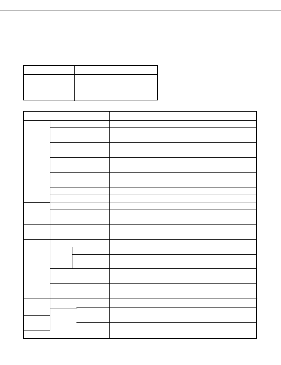
SPECIFICATIONS
Item
FTR-F4
Contact
Arrangement
2 form A (DPST)
Material
Silver alloy
Style
Single
Resistance (initial)
Maximum 100 m (at A 6 VDC)
Rating (resistive)
5A 277 VAC 30 VDC
Maximum Carrying Current
5 A
Maximum Switching Power
1,250VA / 150 W
Maximum Switching Voltage
400 VAC / 300 VDC
Maximum Switching Current
5 A
Minimum Switching Load*
5 VDC, 100mA
Maximum Inrush Current
120 VAC, 51A (TV-3)
Coil Nominal Power(at 20∞C) 0.53 W
Operate Power (at 20∞C) 0.3 W
Operating Temperature
≠40∞C to +70∞C (no frost)
Time Value Operate (at nominal voltage) Maximum 15 ms (not including bounce)
Release (at nominal voltage) Maximum 5 ms (not including bounce)
Insulation
Resistance (at 500 VDC)
Minimum 1,000 M
Dielectric between open contacts 1,000 VAC 1 minute
Strength
between adjacent contacts
3,000VAC 1 minute
between coil and contacts 4,000 VAC 1 minute
Surge Strength
10,000 V (at 1.2 ◊ 50 µs)(between coil and contacts)
Life
Mechanical
2 ◊ 0
6
operations minimum
Electrical Contact rating
◊ 0
5
operations minimum
Lamp load
2.5 ◊ 0
4
operations minimum
Vibration Misoperation
10 to 55 Hz (double amplitude of 1.5 mm)
Endurance
0 to 55 Hz (double amplitude of .5 mm)
Shock Misoperation
200 m/s
2
( ± ms)
Endurance
1,000 m/s
2
(6 ± ms)
Weight
Approximately 2 g
*
Minimum switching loads mentioned above are reference values. Please perform the confirmation test with the actual load
before production since reference values may vary according to switching frequencies, environmental conditions and ex-
pected reliability levels.
n
SAFETY STANDARD AND FILE NUMBERS
UL508
C22.2 No. 1, No. 14
Please note that UL/CSA ratings may differ from the standard ratings. Please request when the approval
markings are required on the cover and/or relay recognized by SEV is required.
e
g
a
tl
o
V
l
a
n
i
m
o
N
g
n
it
a
R
t
c
a
t
n
o
C
C
D
V
8
4
o
t
5
C
A
V
0
2
1
,
3
-
V
T
C
A
V
7
7
2
P
H
4
/
1
C
A
V
5
2
1
P
H
6
/
1
.
s
e
r
C
A
V
7
7
2
/
C
D
V
0
3
A
5
0
0
3
D
y
t
u
d
t
o
li
P

3
FTR-F4 SERIES
n
COIL DATA CHART
MODEL
Nominal
Coil resistance
Operate
Release
Nominal
voltage
(±10%)
voltage
voltage
power
FTR-F4AK005T
5 VDC
47
3.75 VDC
0.25 VDC
530 mW
FTR-F4AK006T
6 VDC
68
4.5 VDC
0.3 VDC
530 mW
FTR-F4AK009T
9 VDC
155
6.75 VDC
0.45 VDC
530 mW
FTR-F4AK012T
12 VDC
270
9.0 VDC
0.6 VDC
530 mW
FTR-F4AK024T
24 VDC
1,100
18.0 VDC
1.2 VDC
530 mW
FTR-F4AK048T
48 VDC
4,400
36.0 VDC
2.4 VDC
530 mW
Note: All values in the table are measured at 20∞C.
Standard type
n
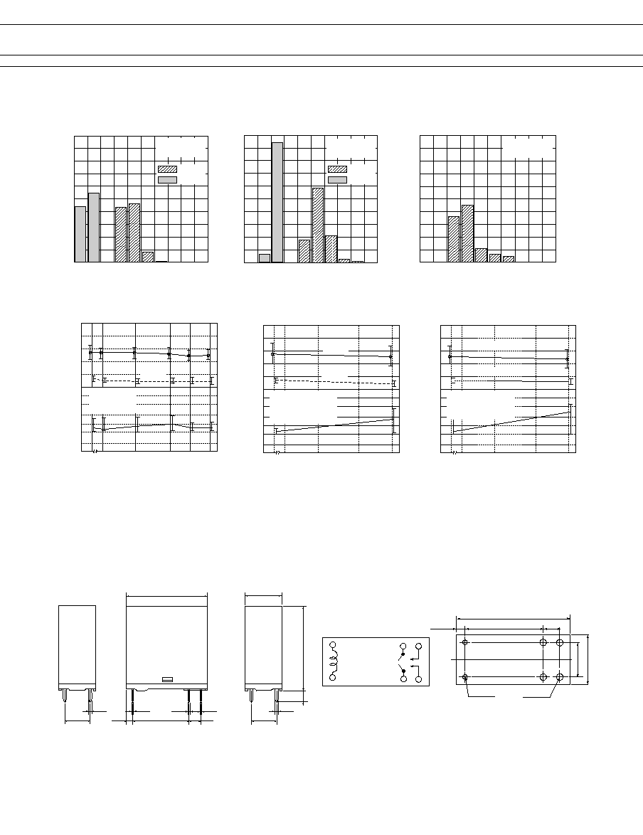
CHARACTERISTIC DATA
20
16
8
12
4
0
0
0.2
0.4
0.6
0.8
1.0
Operate
Release
Coil power (W)
T
ime (ms)
Timing
100
80
60
40
20
0
0.2
0.4
0.6
0.8
1.0
1.2
Coil power (W)
0A
5A
T
emperature rise (∞C)
Coil temperature rise
0
20
40
60
80
100
2.0
1.8
1.6
1.4
1.2
0.6
1.0
0.8
5 A
Ambient temperature (∞C)
Nominal voltage muitiplying factor
Operating range
Operate voltage
of cool coil
Operate voltage
of hot coil
0 A
10
20
50
100
200
500 1000
10
5
2
1
0.5
0.2
Maximum Switching Power
Contact Voltage (V)
Contact Current (A)
AC Resistive
DC Resistive
4
FTR-F4 SERIES
n
REFERENCE DATA
l
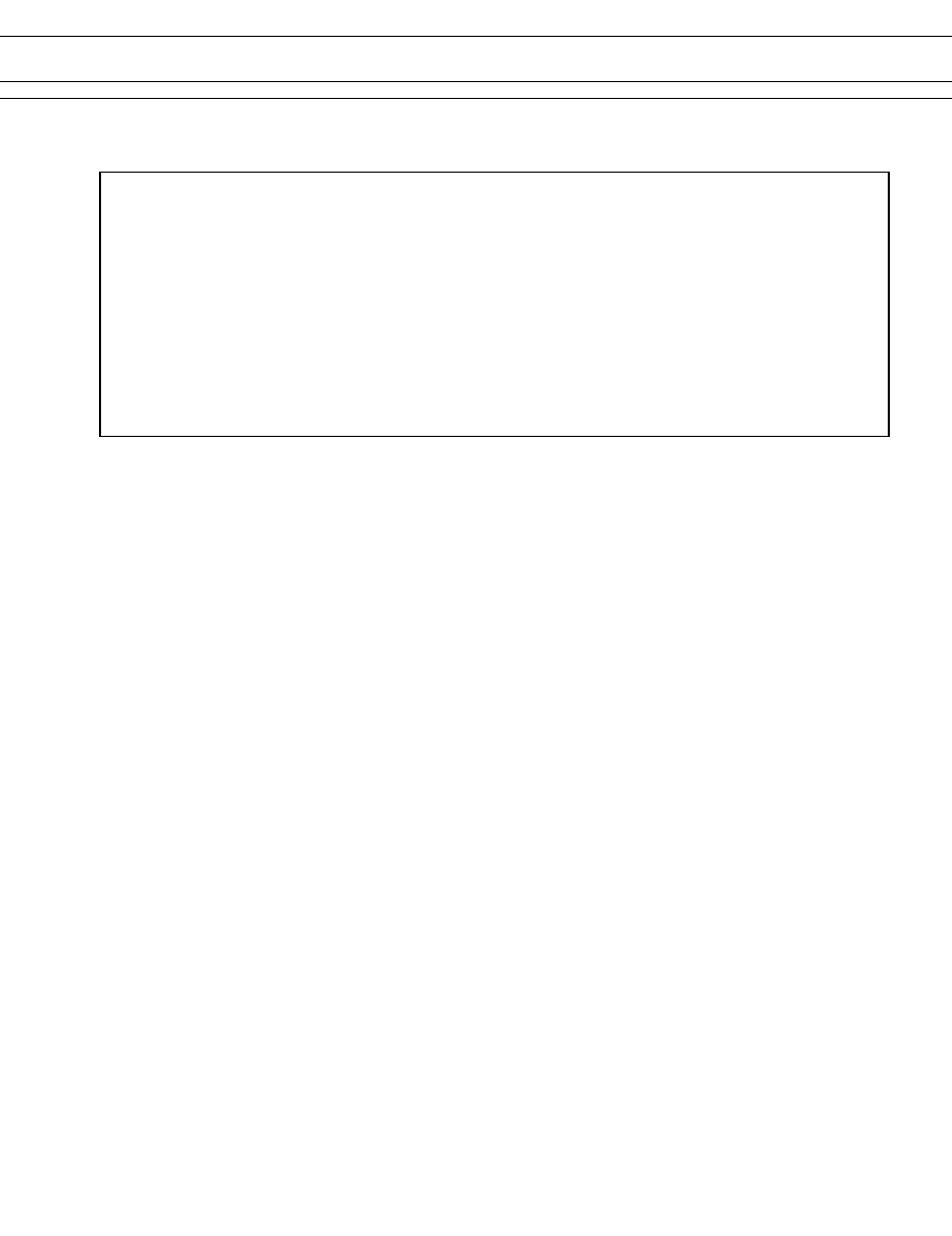
Dimensions
l
Schematics
(BOTTOM VIEW)
FTR-F4 type
n
DIMENSIONS
l
PC board mounting
hole layout
(BOTTOM VIEW)
Unit: mm
2
1
6
4
3
5
2-¯0.9(.035)
4-¯1.3(.051)
7.5(.295)
5(.197)
15(.590)
1.8(.071)
0
10
30
50 60 70
20
40
100
80
60
40
20
100
80 90
Nominal voltage multiplying factor (%)
Operate
Release
Distribution of operate and release voltage
Distribution (%)
FTR-F4AK012T
n=250
0
1
3
5
6
7
2
4
100
80
60
40
20
10
8
9
Time (ms)
Operate
Release
Distribution (%)
Distribution of operate and release time
FTR-F4AK012T
n=250
0
2
4
6
8
10 12 14 16 18 20
100
80
60
40
20
Contact resistance (m )
Distribution (%)
Distribution of contact resistance
FTR-F4AK012T
n=250
2
5
10
1
X
X
X
X
100
50
20
10
5
2
10
8
6
4
2
0
Operation (x10
4
)
Electrical life test
Initial
FTR-F4AK012T
n=8
10 OP/minute
250VAC, 5 A (resistive)
Contact
resistance (m)
V
oltage (V)
Operate
Release
2
5
10
1
A
A
A
A
100
50
20
10
5
2
10
8
6
4
2
0
Operation (x10
4
)
Electrical life test
Initial
FTR-F4AK012T
n=8
10 OP/minute
30VDC, 5 A (resistive)
Contact
resistance (m)
V
oltage (V)
Operate
Release
24.0
+0.3
(.945
+.012
)
25.0
+0.3
(.984
+.012
)
15 (0.590)
5(.197)
1.8(.071)
(0.5(.020)
0.3(.011)
0.4(.016)
1.0(.039)
7.5(.295)
3.3 (.138)
12.0
+0.3
(.472
+.012
)
¯0.5.
(.020)
7.5(.295)
20
100
50
200
10
A
A
A
100
50
20
10
5
2
10
8
6
4
2
0
A
A
A
A
A
A
A
A
A
Operation (x10
4
)
Mechanical life test
Initial
FTR-F4AK012T
n=20
300 OP/minute
Contact
resistance (m)
V
oltage (V)
Operate
Release

5
FTR-F4 SERIES
1. General Information
l
Relays produced after the specific date code that is indicated on each data sheet are lead-free
now. Most of our signal and power relays are lead-free. Please refer to Lead-Free Status Info.
(http://www.fujitsu.com/us/downloads/MICRO/fcai/relays/lead-free-letter.pdf)
l
Lead free solder paste currently used in relays is Sn-3.0Ag-0.5Cu.
l
All signal and most power relays also comply with RoHS. Please refer to individual data
sheets. Relays that are RoHS compliant do not contain the 5 hazardous materials that
are restricted by RoHS directive (lead, mercury, chromium IV, PBB, PBDE).
l
It has been verified that using lead-free relays in leaded assembly process will not cause any
problems (compatible).
l
"LF" is marked on each outer and inner carton. (No marking on individual relays).
l
To avoid leaded relays (for lead-free sample, etc.) please consult with area sales office.
l
We will ship leaded relays as long as the leaded relay inventory exists.
Note: Cadmium was exempted from RoHS on October 21, 2005. (Amendment to Directive 2002/95/EC)
2. Recommended Lead Free Solder Profile
l
Recommended solder paste Sn-3.0Ag-0.5Cu.
RoHS Compliance and Lead Free Relay Information
Reflow Solder condtion
3. Moisture Sensitivity
l
Moisture Sensitivity Level standard is not applicable to electromechanical realys.
4. Tin Whisker
l
Dipped SnAgCu solder is known as low risk tin whisker. No considerable length whisker was found by our in
house test.
We highly recommend that you confirm your actual solder conditions
Flow Solder condtion:
Pre-heating:
maximum 120∞C
Soldering:
dip within 5 sec. at
260∞C soler bath
Solder by Soldering Iron:
Soldering Iron
Temperature: maximum 360∞C
Duration:
maximum 3 sec.
6
FTR-F4 SERIES
Japan
Fujitsu Component Limited
Gotanda-Chuo Building
3-5, Higashigotanda 2-chome, Shinagawa-ku
Tokyo 141, Japan
Tel: (8-3) 5449-700
Fax: (8-3) 5449-2626
Email: promothq@ft.ed.fujitsu.com
Web: www.fcl.fujitsu.com
North and South America
Fujitsu Components America, Inc.
250 E. Caribbean Drive
Sunnyvale, CA 94089 U.S.A.
Tel: (-408) 745-4900
Fax: (-408) 745-4970
Email: marcom@fcai.fujitsu.com
Web: http://www.fujitsu.com/us/services/edevices/components/
Europe
Fujitsu Components Europe B.V.
Diamantlaan 25
232 WV Hoofddorp
Netherlands
Tel: (3-23) 556090
Fax: (3-23) 5560950
Email: info@fceu.fujitsu.com
Web: http://www.fujitsu.com/emea/services/components/
Asia Pacific
Fujitsu Components Asia Ltd.
02E Pasir Panjang Road
#04-0 Citilink Warehouse Complex
Singapore 8529
Tel: (65) 6375-8560
Fax: (65) 6273-302
Email: fcal@fcal.fujitsu.com
Web: http://www.fujitsu.com/sg/services/micro/components/
Fujitsu Components International Headquarter Offices
©2005 Fujitsu Components America, Inc. All rights reserved. All trademarks or registered trademarks are the property off their respective
owners.
Fujitsu Components America does not warrant that the content of datasheet is error free. In a continuing effort to improve our products Fujitsu
Components America, Inc. reserves the right to change specifications/datasheets without prior notice. Rev. 11/18/2005.