40. FTR-P1 Series (p.254-259) 1
s
FEATURES
q
Original construction, where reduction of operational
noise is considered when mounted on PCB, made it
possible to design this quiet relay.
(Average acoustic noise level: 53 dB, distance 10 cm)
q
New types of materials are used for the conductive parts,
allowing this compact relay to carry 20 AMP.
q
Two types of contact material are available for various con-
tact loads.
q
Wider contact gap (0.6 mm) version is also available for
enhanced cut-off ability to overload condition.
s
ORDERING INFORMATION
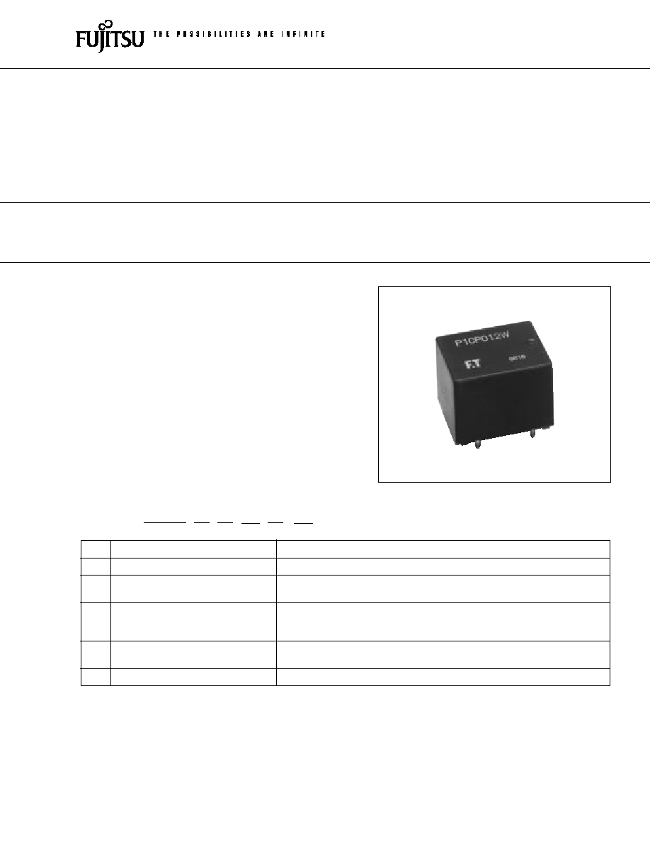
FTR-P1 SERIES
QUIET POWER RELAY
1 POLE--20 A
(FOR AUTOMOTIVE APPLICATIONS)
(a)
Series Name
FTR-P1: FTR-P1 Relay
(b)
Contact Arrangement
C
: 1 form C (SPDT)
(c)
Contact Gap
N
: 0.3 mm gap
P
: 0.6 mm gap
(d)
Nominal Voltage
009
: 9 VDC
010
: 10 VDC
012
: 12 VDC
(e)
Contact Material
N
: Silver-copper-nickel
W
: Silver-tin oxide-indium
(f)
Custom Designation
To be assigned for custom specification
Note: Part No. is printed on the top of relay as follows.
(Example) Designation ordered: FTR-P1CN012N
Stamp: P1CN012N
FTR-P1
C
N
012
N
-**
[Example]
(a)
(b)
(c)
(d)
(e)
(f )
1
2
FTR-P1 SERIES (QUIET TYPE)
s
SPECIFICATIONS
Item
Specifications
Contact
Arrangement
1 form C (SPDT)
Material
Silver-copper-nickel alloy (N type)
Silver-tin oxide-indium (W type)
Voltage Drop (resistance)
Maximum 100 mV (at 2 A 12 VDC)
Ratings
14 VDC/20 A (locked motor load)
14 VDC/inrush 20 A, break 4 A (motor free load)
Maximum Carrying Current
20 A/ 1 hour (25
°
C, 100% rated coil voltage)
Maximum Inrush Current
N Type: 40 A
(reference)
W Type: 60 A
Max. Switching Current (reference)
30 A at 16 VDC
Min. Switching Load*
1
(reference)
6 VDC 1 A
Coil
Operating Temperature Range
40
°
C to +85
°
C (no frost) (reter to the CHARACTERISTIC DATA)
Storage Temperature Range
40
°
C to +100
°
C (no frost)
Time Value
Operate (at nominal voltage)
Maximum 10 ms
Release (at nominal voltage)
Maximum 5 ms
Life
Mechanical
1
×
10
7
operations minimum
Electrical
2
×
10
5
operations minimum (locked motor load)
4
×
10
5
operations minimum (motor free load)
Other
Vibration Resistance
10 to 55 Hz (double amplitude of 1.5 mm)
Shock Misoperation
100 m/s
2
Resistance
Endurance
1,000 m/s
2
Weight
Approximately 10.0 g
*
1
Values when switching a resistive load at normal room temperature and humidity, and in a clean environment.
The minimum applicable load varies with the switching frequency and operating environment.
s
COIL DATA CHART
MODEL
Nominal
Coil
Must operate
Must
Thermal
voltage
resistance
voltage
release
resistance
N TYPE
W TYPE
(
±
10%)
voltage
FTR-P1CN009N
FTR-P1CN009W
9 VDC
135
5.4 V (at 20
°
C)
0.7 V
6.8 V (at 85
°
C)
FTR-P1CN010N
FTR-P1CN010W
10 VDC
180
6.3 V (at 20
°
C)
0.8 V
73
°
C/W
7.9 V (at 85
°
C)
FTR-P1CN012N
FTR-P1CN012W
12 VDC
240
7.3 V (at 20
°
C)
0.9 V
9.2 V (at 85
°
C)
q
0.3 mm contact gap type
3
FTR-P1 SERIES (QUIET TYPE)
MODEL
Nominal
Coil
Must operate
Must
Thermal
voltage
resistance
voltage
release
resistance
N TYPE
W TYPE
(
±
10%)
voltage
FTR-P1CP009N
FTR-P1CP009W
9 VDC
100
5.4 V (at 20
°
C)
0.7 V
6.8 V (at 85
°
C)
FTR-P1CP010N
FTR-P1CP010W
10 VDC
135
6.3 V (at 20
°
C)
0.8 V
65
°
C/W
7.9 V (at 85
°
C)
FTR-P1CP012N
FTR-P1CP012W
12 VDC
180
7.3 V (at 20
°
C)
0.9 V
9.2 V (at 85
°
C)
Note: Values in the table of coil resistance and must release voltage are measured at 20
°
C.
q
0.6 mm Contact Gap Type
s
SUITABLE APPLICATION
CONTACT MATERIAL
SUITABLE LOAD
N: Silver-copper-nickel
Intermittent wiper
W: Silver-tin oxide-indium
Door lock
Power window
Solenoids, etc. (locked rotor)
s
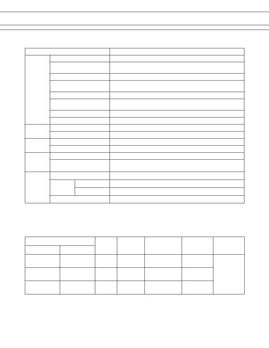
CHARACTERISTIC DATA
1. MAXIMUM BREAK CAPACITY
2. LIFE
Voltage between contacts (V)
10
10
15
12
20
25
30
35
40
50
Contact switching current (A)
20
15
25
35
30
40 50
0.3 mm gap
0.3 mm gap
0.6 mm gap
0.6 mm gap
Locked motor
load
Resistive load
Locked motor current (A)
14 VDC Motor locked load
10
5
10
20
30
Number of operations (x10
4
)
20
15
25
35
45
30
40 50
4
FTR-P1 SERIES (QUIET TYPE)
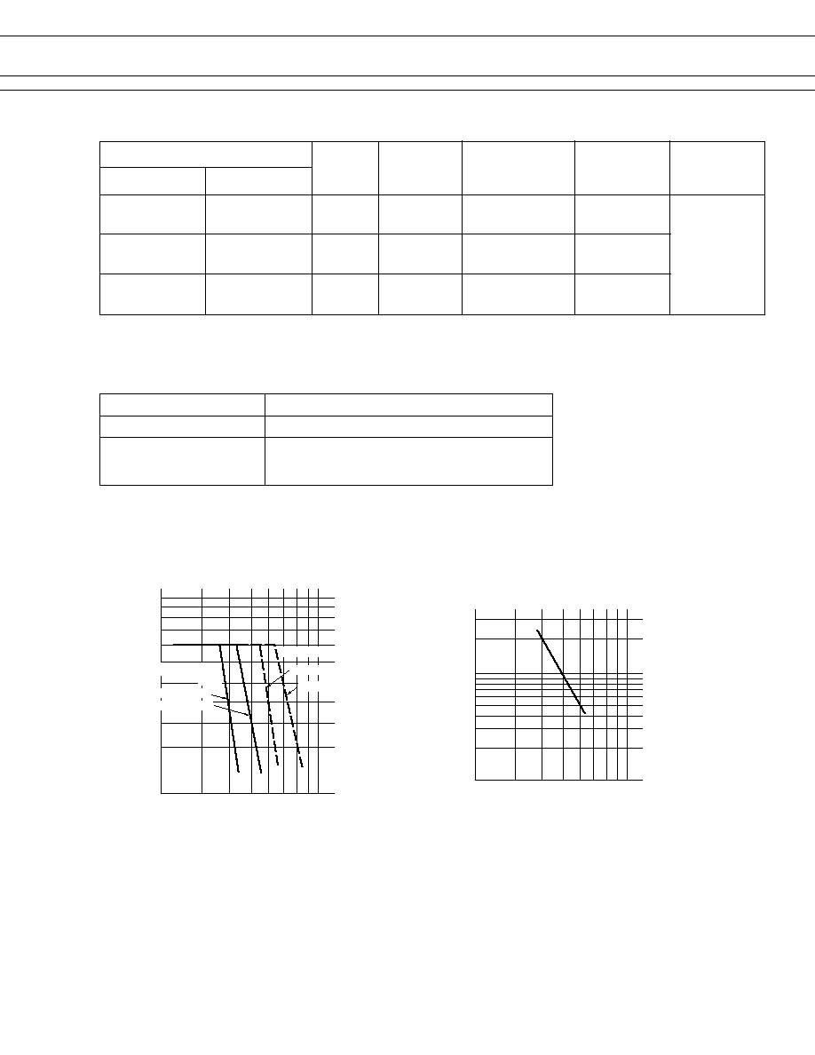
3. LIFE TEST (EXAMPLE)
· Test item
14 V DC-20 A
Motor Lock
200,000 operations
minimum
· Test circuit
· Current wave form
· Shift of pick-up drop-out voltage
· Shift of contact resistance
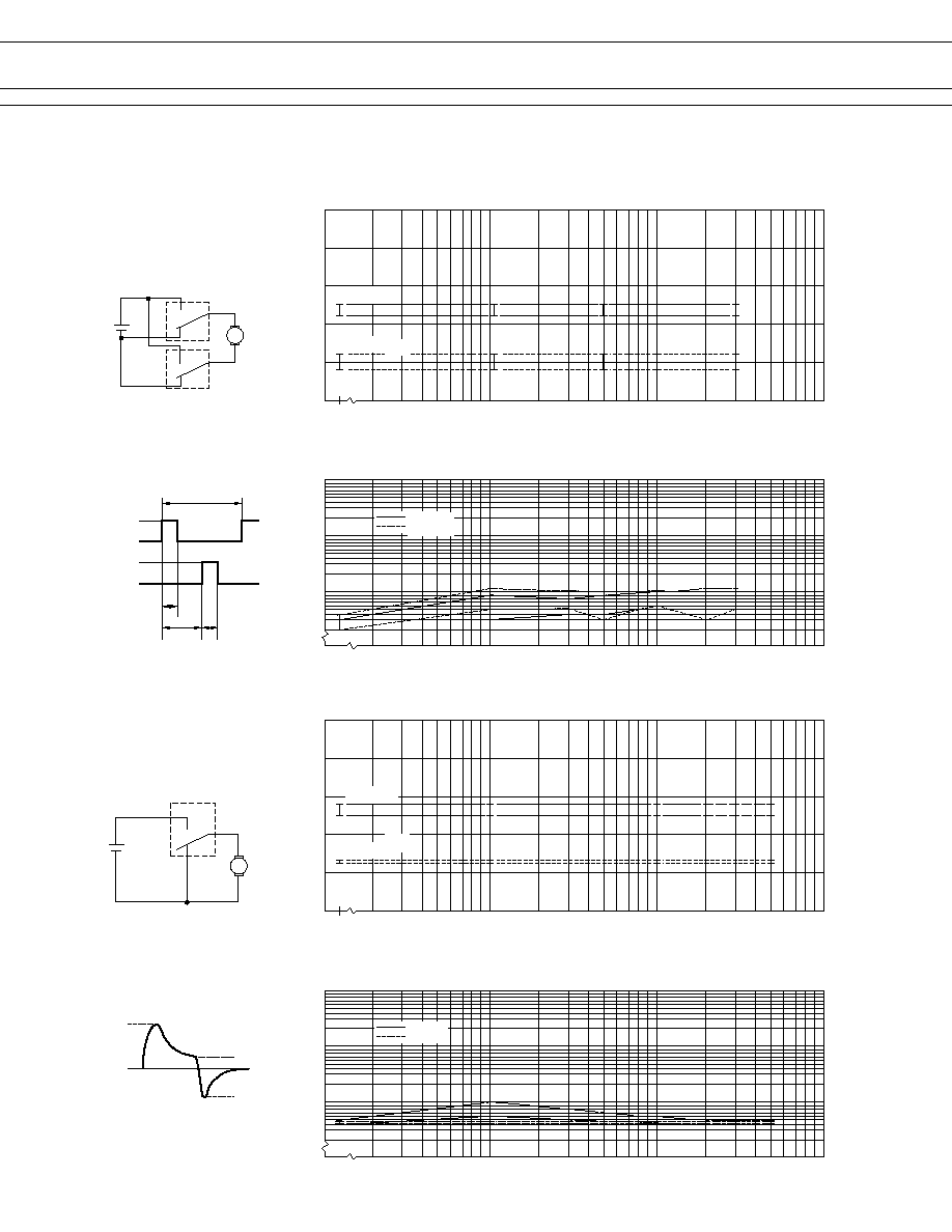
· Test item
14 V DC-20 A
motor free
400,000 operations
minimum
· Test circuit
· Current wave form
· Shift of pick-up drop-out voltage
· Shift of contact resistance
0
100
10
1
20
40
60
80
100
(RL-1)
20 sec
20 A
0 A
20 A
0 A
(RL-2)
0.3 sec
10 sec
0.3 sec
100
10
1
1000
100
10
(Measured at 6 V-1 A)
0
100
10
1
20
40
60
80
100
100
10
1
1000
100
10
(Measured at 6 V-1 A)
M
N.O.
N.C.
0 A
4 A
20 A
16 A
M
RL-1
RL-2
N.O.
N.C.
N.O.
N.C.
PICK-UP
Initial
Percent of rated coil voltage (%)
Number of operations (x10
4
)
Break
Make
Contact Resistance (m
)
Initial
Initial
Percent of rated coil voltage (%)
Number of operations (x10
4
)
Break
Make
Contact Resistance (m
)
Initial
PICK-UP
DROP-OUT
DROP-OUT
5
FTR-P1 SERIES (QUIET TYPE)
4. COIL TEMPERATURE RISE
5. OPERATING COIL VOLTAGE RANGE (EXAMPLE)
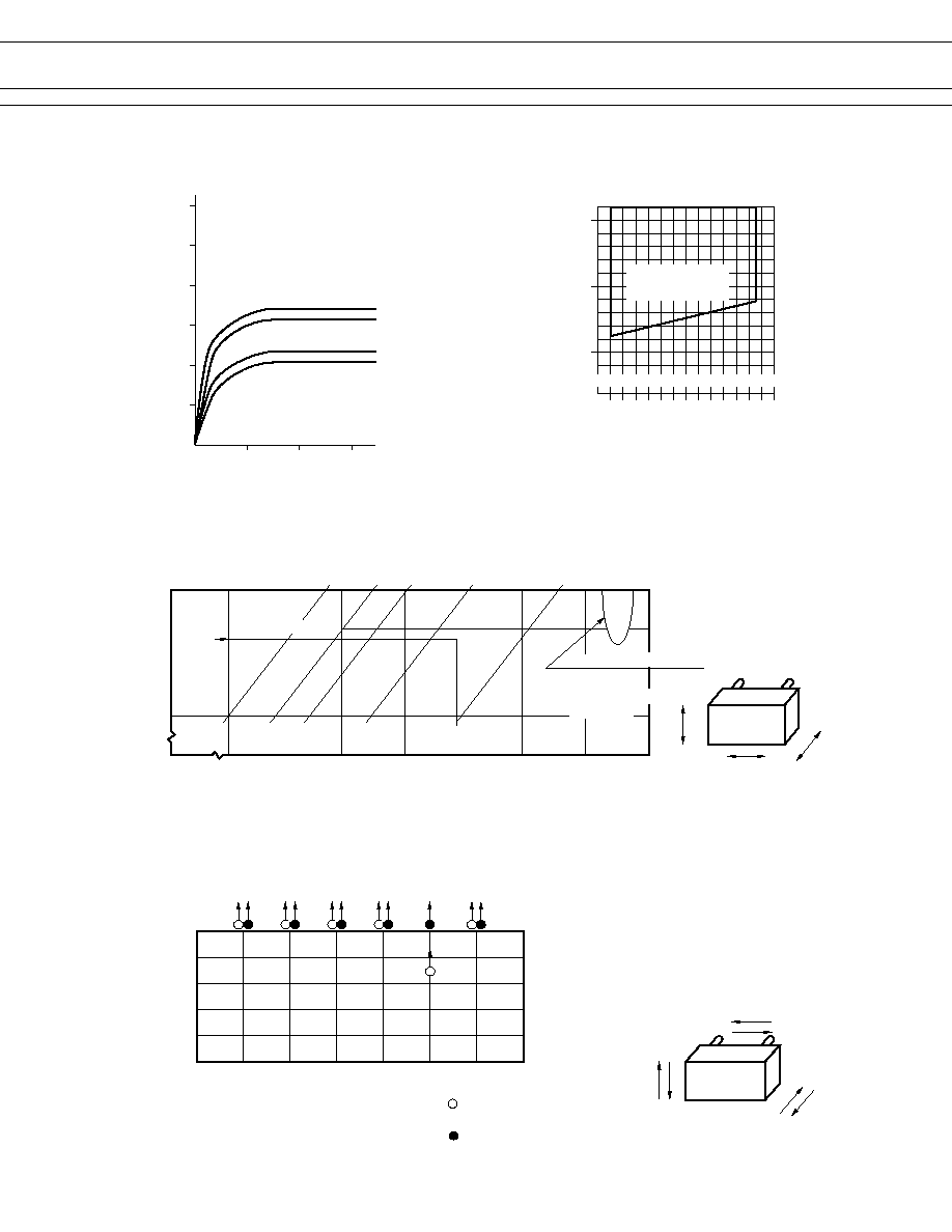
6. VIBRATION RESISTANCE CHARACTERISTICS
7. SHOCK RESISTANCE CHARACTERISTICS
Coil temperature rise (
°
C)
Applied time (minutes)
0
0
10
20
30
20
40
60
80
100
120
0.8 W
at 20°C
0.6 W
(2) carrying current :
applied coil power 10 A
0.8 W
0.6 W
(1) carrying current :
applied coil power 0 A
30
0
50
100
5
10
15
Applied voltage to the coil
Operating temperature (°C)
(V)
CONTINUOUSLY
APPLICABLE COIL
VOLTAGE RANGE
FTR-P1
Y
Z
X
Frequency : 10~2000 Hz
Acceleration : 100 m/s
2
maximum
Vibration direction : see diagram
Detection level : chatter of 100
µ
s minimum
Acceleration
(m/s
2
)
10
50
100
10
50
100
500
1000
2000
5
1
0.5
0.1
0.01
Dual amplitude (mm)
Frequency (Hz)
Automotive
electronic standard
44 m/s
2
Range where chattering occurs
N.O. contact
coil not energized
on Z-direction
0
200
400
600
800
1,000
X1
X2
Y1
Y2
Z1
Z2
Shock level
(m/s
2
)
Shock direction
: N.C. contact
(coil de-energized)
Shock application time : 11 ms, half-sine wave
Test material : coil, energized and de-energized
Shock direction: see diagram
Detection level : chatter of 100
µ
s minimum
FTR-P1
Z2
Z1
Y1
Y2
X2
X1
: N.C. contact
(coil energized)