
s
FEATURES
q
Low operating sound
An original silent mechanism decreases the propagation of operat-
ing sound when mounted on a PCB. (Average sound pressure:
50dB at 5 cm).
q
Compact, high density package
350 mm
2
mounting area. (11% less than the FBR 510 series non-
quiet twin relay).
q
High sensitivity, low power consumption
(nominal power consumption: 450 mW).
q
High capacity
Heat dissipation is high due to a single cover structure.
q
Ease of PCB layout
The FTR-P2 incorporates internal H-Bridge connections typically
used in reversing applications. All terminals are on the perimeter.
q
High breaking capability.
In addition to the standard gap product (0.3 mm), a higher gap
product (0.6 mm), suitable for over voltage breaking can be sup-
plied.
q
Typical applications
Power window, Doorlock, Power seat, Wiper (for H-Bridge circuit)
1
Note: The part number is stamped on the relay cover as in the following example:
(Example)
Ordering part number: FTR-P2CN012W1
Stamped part number: P2CN012W1
SILENT TWIN RELAY FOR AUTOMOTIVE
APPLICATIONS
1POLE X 2, H-BRIDGE, 25A
FTR-P2 SERIES
(a)
Series Name
FTR-P2 : FTR-P2 Series
(b)
Contact Arrangement
C
: 1 FormC x 2
(c)
Contact Gap
N
: 0.3 mm gap
P
: 0.6mm gap
(d)
Nominal Voltage
009: 9 VDC
010: 10 VDC
012: 12 VDC
(e)
Contact Material
W1
: Silver-Tin-Oxide-Indium Oxide
(f)
Special product
Symbol to specify special specification product
specification
s
ORDERING INFORMATION
FTR-P2
C
N
012 W1
**
[Example]
(a)
(b)
(c)
(d)
(e)
(f )

2
FTR-P2 SERIES
s
SPECIFICATIONS
s
COIL DATA
*This is the standard value of the minimum load level. This value may differ depending on the switching frequency,
environmental conditions and target reliability standard. We recommend to check this value by an actual load prior to use.
e
m
a
N
t
c
u
d
o
r
P
l
i
o
C
l
a
n
i
m
o
N
e
g
a
t
l
o
V
*
e
c
n
a
t
s
i
s
e
R
l
i
o
C
)
%
0
1
±
(
r
e
w
o
P
n
o
i
t
p
m
u
s
n
o
C
l
i
o
c
l
a
n
i
m
o
n
t
a
*
e
g
a
t
l
o
v
e
t
a
r
e
p
O
t
s
u
M
*
e
g
a
t
l
o
V
e
s
a
e
l
e
R
t
s
u
M
e
g
a
t
l
o
V
1
W
9
0
0
N
C
2
P
-
R
T
F
V
9
C
D
0
8
1
W
m
0
5
4
)
∞
0
2
(
V
5
.
5
)
∞
5
8
(
V
9
.
6
2
7
.
0
1
W
0
1
0
N
C
2
P
-
R
T
F
V
0
1
C
D
0
2
2
W
m
5
5
4
)
∞
0
2
(
V
3
.
6
)
∞
5
8
(
V
9
.
7
8
.
0
1
W
2
1
0
N
C
2
P
-
R
T
F
V
2
1
C
D
0
2
3
W
m
0
5
4
)
∞
0
2
(
V
3
.
7
)
∞
5
8
(
V
2
.
9
6
9
.
0
m
e
t
I
n
o
i
t
a
c
i
f
i
c
e
p
S
k
r
a
m
e
R
t
c
a
t
n
o
C
t
n
e
m
e
g
n
a
r
r
A
e
g
d
i
r
B
-
H
n
i
2
x
C
m
r
o
F
1
l
a
i
r
e
t
a
M
e
d
i
x
O
m
u
i
d
n
I
-
e
d
i
x
O
n
i
T
-
r
e
v
li
S
p
o
r
d
e
g
a
t
l
o
V
m
u
m
i
x
a
m
m
0
0
1
C
D
V
2
1
,
A
2
t
a
d
e
r
u
s
a
e
M
g
n
i
t
a
r
t
c
a
t
n
o
C
)
d
e
k
c
o
l
r
o
t
o
m
(
A
5
2
,
V
4
1
C
D
t
n
e
r
r
u
C
g
n
i
y
r
r
a
C
m
u
m
i
x
a
M
d
e
il
p
p
a
e
g
a
t
l
o
v
l
a
n
i
m
o
n
,
C
5
2
(
r
u
o
h
1
/
A
5
2
)
li
o
c
o
t
*
d
a
o
L
m
u
m
i
n
i
M
A
1
V
6
e
u
l
a
v
e
c
n
e
r
e
f
e
R
li
o
C
e
g
n
a
R
e
r
u
t
a
r
e
p
m
e
T
g
n
i
t
a
r
e
p
O
C
∞
5
8
+
o
t
C
∞
0
4
-
t
s
o
r
f
o
N
e
g
n
a
R
e
r
u
t
a
r
e
p
m
e
T
e
g
a
r
o
t
S
C
∞
0
0
1
+
o
t
C
∞
0
4
-
e
m
i
T
)
e
g
a
t
l
o
v
l
a
n
i
m
o
n
t
a
(
e
t
a
r
e
p
O
m
u
m
i
x
a
m
s
m
0
1
s
i
e
g
a
t
l
o
v
li
o
c
l
a
n
i
m
o
n
n
e
h
W
,
d
e
v
o
m
e
r
r
o
,
li
o
c
o
t
d
e
il
p
p
a
.
e
d
o
i
d
o
n
)
e
g
a
t
l
o
v
l
a
n
i
m
o
n
t
a
(
e
s
a
e
l
e
R
m
u
m
i
x
a
m
s
m
5
e
f
i
L
l
a
c
i
n
a
h
c
e
M
m
u
m
i
n
i
m
s
n
o
i
t
a
r
e
p
o
n
o
il
li
m
0
1
l
a
c
i
r
t
c
e
l
E
m
u
m
i
n
i
m
s
n
o
i
t
a
r
e
p
o
K
0
0
1
g
n
i
t
a
r
t
c
a
t
n
o
c
t
A
r
e
h
t
O
)
l
a
n
o
i
t
a
r
e
p
O
(
e
c
n
a
t
s
i
s
e
r
n
o
i
t
a
r
b
i
V
e
d
u
t
il
p
m
a
e
l
b
u
o
d
m
m
5
.
1
,
z
H
5
5
-
0
1
z
H
5
5
@
G
3
1
.
9
=
k
c
o
h
S
e
c
n
a
t
s
i
s
e
r
l
a
n
o
i
t
a
r
e
p
O
s
/
m
0
0
1
2
)
G
0
1
(
m
u
m
i
n
i
m
e
g
a
m
a
D
o
N
s
/
m
0
0
0
1
2
)
G
0
0
1
(
m
u
m
i
n
i
m
t
h
g
i
e
W
s
m
a
r
g
3
1
y
l
e
t
a
m
i
x
o
r
p
p
A
e
r
u
s
s
e
r
p
d
n
u
o
s
e
g
a
r
e
v
A
m
c
5
t
a
B
d
0
5
y
l
e
t
a
m
i
x
o
r
p
p
A
g
n
i
t
h
g
i
e
w
A

3
FTR-P2 SERIES
1. LIFE TEST (EXAMPLES)
∑ Test circuit
∑ Current wave form
∑ Shift of pick-up drop-out voltage
∑ Change in contact resistance
∑ Test item
14 V DC,
inrush current: 17A
motor free
300K operations minimum
0.25 seconds ON,
9.75 seconds OFF
∑ Test circuit
∑ Current wave form
∑ Change in pick-up drop-out voltage
∑ Change in contact resistance
PICK-UP
Initial
Percent of nominal coil voltage (%)
Contact Resistance (m
)
Initial
Initial
Percent of nominal coil voltage
(%)
Contact Resistance (m
)
Initial
PICK-UP
DROP-OUT
DROP-OUT
∑ Test item
14 V DC-25 A
Motor Lock
100K operations
minimum
(RL-1)
20 sec
20 A
0 A
20 A
0 A
(RL-2)
0.25 sec
10 sec
0.25 sec
0 A
1.5 A
17 A
12 A
M
M
20
50
100
500
1000
0
20
40
60
80
100
Number of operations (x 10
3
times)
1
10
100
1000
20
50
100
500
1000
(Measured at DC 6V 1A wet)
Number of operations (x 10
3
times)
20
50
100
500
1000
0
20
40
60
80
100
Number of operations (x 10
3
times)
1
10
100
1000
20
50
100
500
1000
(Measured at DC 6V 1A wet)
Number of operations (x 10
3
times)
s
CHARACTERISTIC DATA
Notes: 1. Test was done on
one side of twin relay
2. NC contacts provide
dynamic brake circuits

4
FTR-P2 SERIES
3. COIL TEMPERATURE RISE
100
80
60
40
20
0
0
Ambient temperature:20
∞
C,
one coil energized, 0.45 W coil power
(3) Contact carrying current: 20A
(2) Contact carrying current: 10A
10
20
30
Applied time (minutes)
Coil temperature rise (degree
∞
C)
4. OPERATING COIL VOLTAGE RANGE
140
120
100
80
60
40
-30 -20
0
20
40
60
80
100
Intermittent coil operation with 10A
carrying current
Must-operate voltage
Continuous coil
power range
Ambient temperature (
∞
C)
Ratio to nominal coil voltage (%)
100
50
20
10
5
2
1
10
13
15
17
20
25
30
Switching Current (A)
Voltage between contacts (VDC)
Motor lock load
FTR-P2CN
2. MAXIMUM BREAK CAPACITY
5
FTR-P2 SERIES
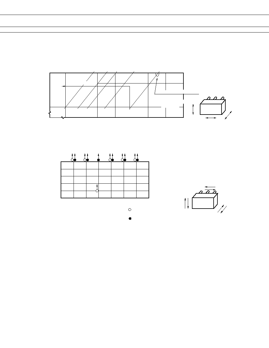
6. SHOCK RESISTANCE CHARACTERISTIC
FTR-P2
Y
Z
X
Frequency : 10~2000 Hz
Acceleration : 100 m/s
2
maximum
Vibration direction : see drawing below
Detection level : generation of 1 ms
Acceleration
(m/s
2
)
10
50
100
10
50
100
500
1000
2000
5
1
0.5
0.1
0.01
Dual amplitude (mm)
Frequency (Hz)
Automotive
electronic standard
44 m/s
2
Range where chattering occurs
Break contact
Coil deenergization
on Y-direction
or longer chattering
0
200
400
600
800
1,000
X1
X2
Y1
Y2
Z1
Z2
impact value (m/s
2
)
Impact direction
: Break contact
(coil de-energized)
Impact apply time : 11
±
1 ms, half-sine wave
Test condition: coil, energized and de-energized
Impact direction: see drawing below
Detection level : generation of 1ms or longer
FTR-P2
Z2
Z1
Y1
Y2
X2
X1
: Make contact
(coil energized)
contact chattering
5. VIBRATION RESISTANCE CHARACTERISTICS