Äîêóìåíòàöèÿ è îïèñàíèÿ www.docs.chipfind.ru
FTR-P5 SERIES
n
ORDERING INFORMATION
FTR-P5 C N 02 W **
[Example]
(a)
(b) (c) (d) (e)
(f)
n
FEATURES
l
Lowoperatingsound
Anoriginalsilentmechanismdecreasesthepropagationof
operatingsoundwhenmountedonaPCB.(Averagesound
pressure:50dBat5cm).
l
Compact,highdensitypackage
98mm
2
mountingarea.(46%lessthantheFTR-PSe-
riesquiettwinrelay).
l
Highsensitivity,lowpowerconsumption
(nominalpowerconsumption:450mW).
l
Highcapacity
Heatdissipationishighduetoasinglecoverstructure.
l
EaseofPCBlayout
Allterminalsareontheperimeter.
l
Highbreakingcapability.
Inadditiontothestandardgapproduct(0.3mm),ahigher
gapproduct(0.6mm),suitableforovervoltagebreaking
canbesupplied.
l
Typicalapplications:
Wiper/IWW,Powerwindow,Doorlock,Powerseat
Sunroof,Interiorlighting,Fan
l
RoHScompliantsincedatecode:0623
Pleaseseepage8formoreinformation
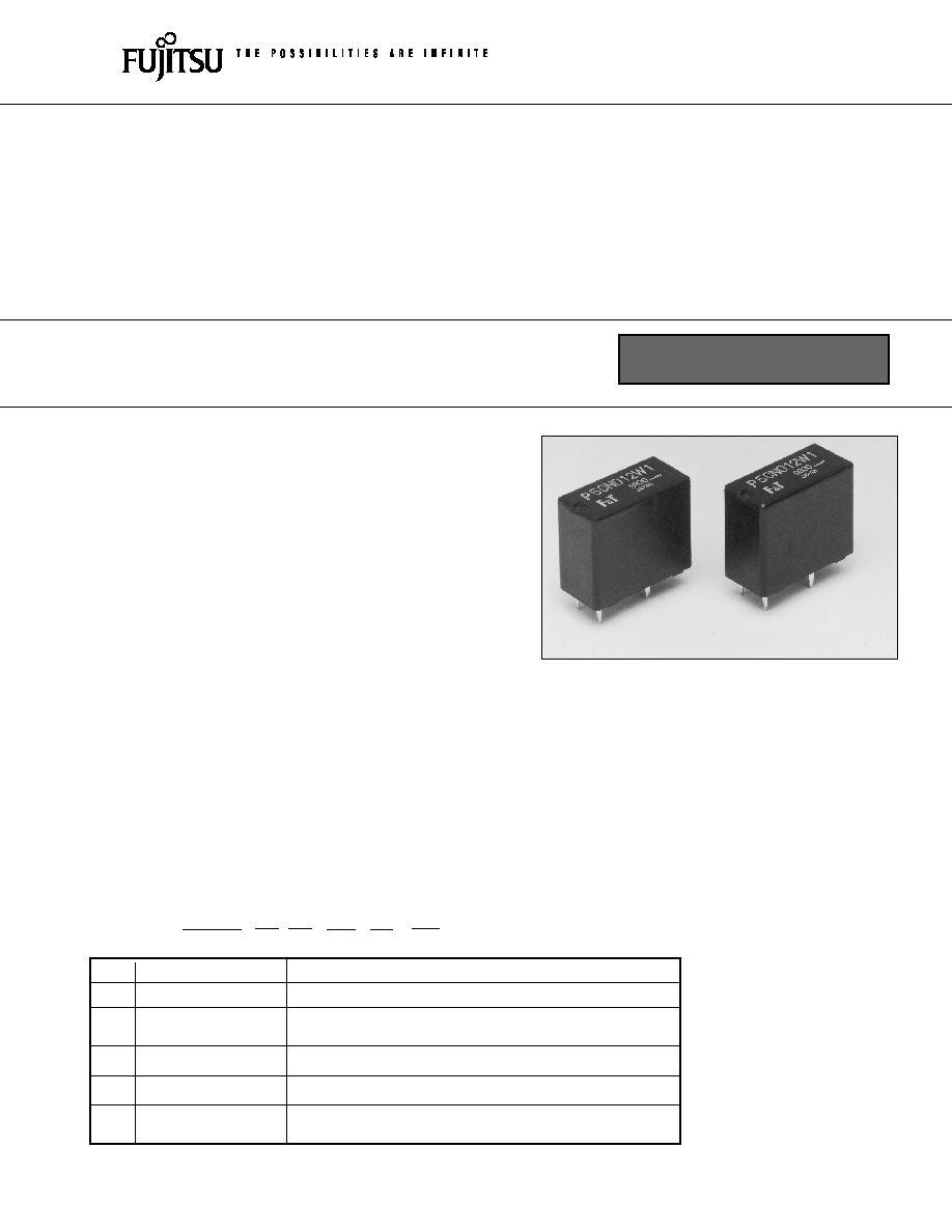
FTR-P5 SERIES
SILENT RELAY FOR
AUTOMOTIVE APPLICATIONS
1 POLE--25 A
Note:Thepartnumberontherelaycoverdoesnotinclude'FTR'
Example:
Orderingpartnumber:FTR-P5CN02W
Stampedpartnumber:P5CN02W
(a)
SeriesName
FTR-P2 :FTR-P2Series
(b)
ContactArrangement C
:FormC
(c)
ContactGap
N
:0.3mmgap
P
:0.6mmgap
(d)
NominalVoltage
009:9VDC
00:0VDC
02:2VDC
(e)
ContactMaterial
W
:Silver-Tin-OxideIndiumOxide
(f)
Specialproduct
Symboltospecifyspecialspecificationproduct
specification
RoHS compliant
2
FTR-P5 SERIES
n
SPECIFICATIONS
n
COIL DATA
*Thisisthestandardvalueoftheminimumloadlevel.Thisvaluemaydifferdependingontheswitchingfrequency,environmental
conditionsandtargetreliabilitystandard.Werecommendtocheckthisvaluebyanactualloadpriortouse.
m
e
tI
n
o
it
a
c
if
i
c
e
p
S
k
r
a
m
e
R
t
c
a
t
n
o
C
t
n
e
m
e
g
n
a
r
r
A
C
m
r
o
F
1
l
a
ir
e
t
a
M
e
d
i
x
O
m
u
i
d
n
I-
e
d
i
x
O
n
i
T
-
r
e
v
li
S
p
o
r
d
e
g
a
tl
o
V
m
u
m
i
x
a
m
m
0
0
1
C
D
V
2
1
,
A
2
t
a
d
e
r
u
s
a
e
M
g
n
it
a
r
t
c
a
t
n
o
C
)
d
e
k
c
o
l
r
o
t
o
m
(
A
5
2
,
V
4
1
C
D
t
n
e
r
r
u
C
g
n
i
y
r
r
a
C
m
u
m
i
x
a
M
d
e
il
p
p
a
e
g
a
tl
o
v
l
a
n
i
m
o
n
,
C
5
2
(
r
u
o
h
1
/
A
5
2
)l
i
o
c
o
t
*
d
a
o
L
m
u
m
i
n
i
M
A
1
V
6
e
u
l
a
v
e
c
n
e
r
e
f
e
R
li
o
C
e
g
n
a
R
e
r
u
t
a
r
e
p
m
e
T
g
n
it
a
r
e
p
O
C
°
5
8
+
o
t
C
°
0
4
-
t
s
o
rf
o
N
e
g
n
a
R
e
r
u
t
a
r
e
p
m
e
T
e
g
a
r
o
t
S
C
°
0
0
1
+
o
t
C
°
0
4
-
e
m
i
T
)
e
g
a
tl
o
v
l
a
n
i
m
o
n
t
a
(
e
t
a
r
e
p
O
m
u
m
i
x
a
m
s
m
0
1
s
i
e
g
a
tl
o
v
li
o
c
l
a
n
i
m
o
n
n
e
h
W
,
d
e
v
o
m
e
r
r
o
,l
i
o
c
o
t
d
e
il
p
p
a
.
e
d
o
i
d
o
n
)
e
g
a
tl
o
v
l
a
n
i
m
o
n
t
a
(
e
s
a
e
l
e
R
m
u
m
i
x
a
m
s
m
5
e
fi
L
l
a
c
i
n
a
h
c
e
M
m
u
m
i
n
i
m
s
n
o
it
a
r
e
p
o
n
o
il
li
m
0
1
l
a
c
ir
t
c
e
l
E
m
u
m
i
n
i
m
s
m
o
it
a
r
e
p
o
K
0
0
1
g
n
it
a
r
t
c
a
t
n
o
c
t
A
r
e
h
t
O
)l
a
n
o
it
a
r
e
p
O
(
e
c
n
a
t
s
i
s
e
r
n
o
it
a
r
b
i
V
e
d
u
ti
l
p
m
a
e
l
b
u
o
d
m
m
5
.
1
,
z
H
5
5
-
0
1
z
H
5
5
@
G
3
1
.
9
=
k
c
o
h
S
e
c
n
a
t
s
i
s
e
r
l
a
n
o
it
a
r
e
p
O
s
/
m
0
0
1
2
)
G
0
1
(
m
u
m
i
n
i
m
e
g
a
m
a
D
o
N
s
/
m
0
0
0
1
2
)
G
0
0
1
(
m
u
m
i
n
i
m
t
h
g
i
e
W
s
m
a
r
g
3
1
y
l
e
t
a
m
i
x
o
r
p
p
A
e
r
u
s
s
e
r
p
d
n
u
o
s
e
g
a
r
e
v
A
m
c
5
t
a
B
d
0
5
y
l
e
t
a
m
i
x
o
r
p
p
A
g
n
it
h
g
i
e
w
A
e
m
a
N
t
c
u
d
o
r
P
li
o
C
l
a
n
i
m
o
N
e
g
a
tl
o
V
*
e
c
n
a
t
s
i
s
e
R
li
o
C
)
%
0
1
±
(
r
e
w
o
P
n
o
it
p
m
u
s
n
o
C
li
o
c
l
a
n
i
m
o
n
t
a
*
e
g
a
tl
o
v
e
t
a
r
e
p
O
t
s
u
M
*
e
g
a
tl
o
V
e
s
a
e
l
e
R
t
s
u
M
e
g
a
tl
o
V
1
W
9
0
0
N
C
5
P
-
R
T
F
V
9
C
D
0
8
1
W
m
0
5
4
)
°
0
2
(
V
5
.
5
)
°
5
8
(
V
9
.
6
2
7
.
0
1
W
0
1
0
N
C
5
P
-
R
T
F
V
0
1
C
D
0
2
2
W
m
5
5
4
)
°
0
2
(
V
3
.
6
)
°
5
8
(
V
9
.
7
8
.
0
1
W
2
1
0
N
C
5
P
-
R
T
F
V
2
1
C
D
0
2
3
W
m
0
5
4
)
°
0
2
(
V
3
.
7
)
°
5
8
(
V
2
.
9
6
9
.
0
3
FTR-P5 SERIES
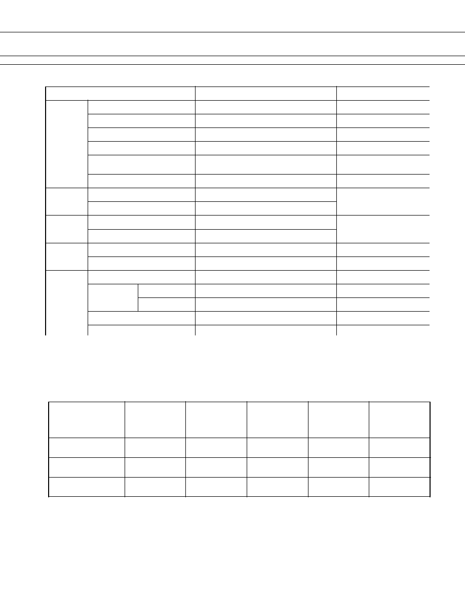
1. LIFE TEST (EXAMPLES)
·Testcircuit
·Currentwaveform
·Shiftofpick-updrop-outvoltage
·Changeincontactresistance
·Testitem
4VDC,
inrushcurrent:30A
motorfree
300Koperationsminimum
0.25secondsON,
9.75secondsOFF
·Testcircuit
·Currentwaveform
·Changeinpick-updrop-outvoltage
·Changeincontactresistance
PICK-UP
Initial
Percent
of
nominal
coil
voltage
(%)
Contact
Resistance
(m)
Initial
Initial
Percent
of
nominal
coil
voltage
(%)
Contact
Resistance
(m)
Initial
PICK-UP
DROP-OUT
DROP-OUT
·Testitem
4VDC-25A
MotorLock
00Koperations
minimum*
n
CHARACTERISTIC DATA
Note:NCcontactsprovide
dynamicbrakecircuit
20
50
100
500
100
0
20
40
60
80
100
Number of operations (x 10
3
times)
1
10
100
1000
20
50
100
500
1000
(Measured at DC 6V 1A wet)
Number of operations (x 10
3
times)
2
5
10
50
100
0
20
40
60
80
100
Number of operations (x 10
3
times)
1
10
100
1000
20
50
100
500
1000
(Measured at DC 6V 1A wet)
Number of operations (x 10
3
times)
(RL-1)
20 sec
25 A
0 A
25 A
0 A
(RL-2)
0.25 sec
10 sec
0.25 sec
M
RL-1
RL-2
N.O.
N.C.
N.O.
N.C.
* 1 operation = 1 forward
and 1 reverse
M
N.O.
RL
N.C.
0 A
5 A
30 A
20 A
4
FTR-P5 SERIES
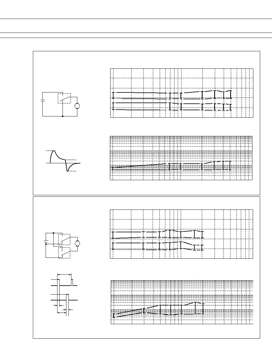
3. COIL TEMPERATURE RISE
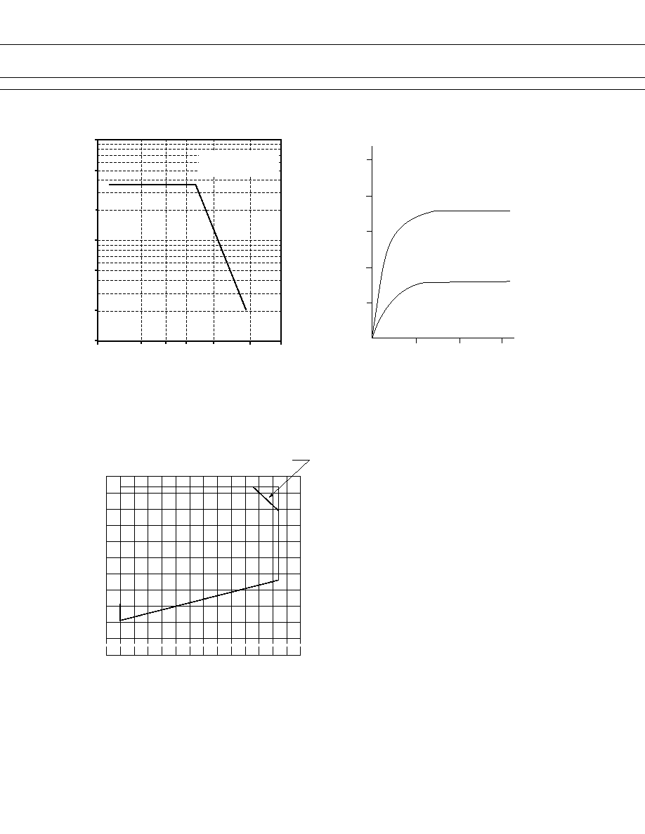
4. OPERATING COIL VOLTAGE RANGE
2. MAXIMUM BREAK CAPACITY
100
50
20
10
5
2
1
10
13
15 17 20
25
30
Switching Current (A)
Voltage between contacts (VDC)
Motor lock load
FTR-P5CN
100
80
60
40
20
0
0
Ambient temperature:20C,
one coil energized, 0.45 W coil power
(3) Contact carrying current: 20A
(2) Contact carrying current: 10A
10
20
30
Applied time (minutes)
C
o
i
l
t
e
m
p
e
r
a
t
u
r
e
r
i
s
e
(
d
e
g
r
e
e
C
)
140
120
100
80
60
40
-30 -20
0
20
40
60
80
100
Intermittent coil operation with 10A
carrying current
Must-o
perate
voltag
e
Continuous coil
power range
Ambient temperature (C)
R
a
t
i
o
t
o
n
o
m
i
n
a
l
c
o
i
l
v
o
l
t
a
g
e
(
%
)
5
FTR-P5 SERIES
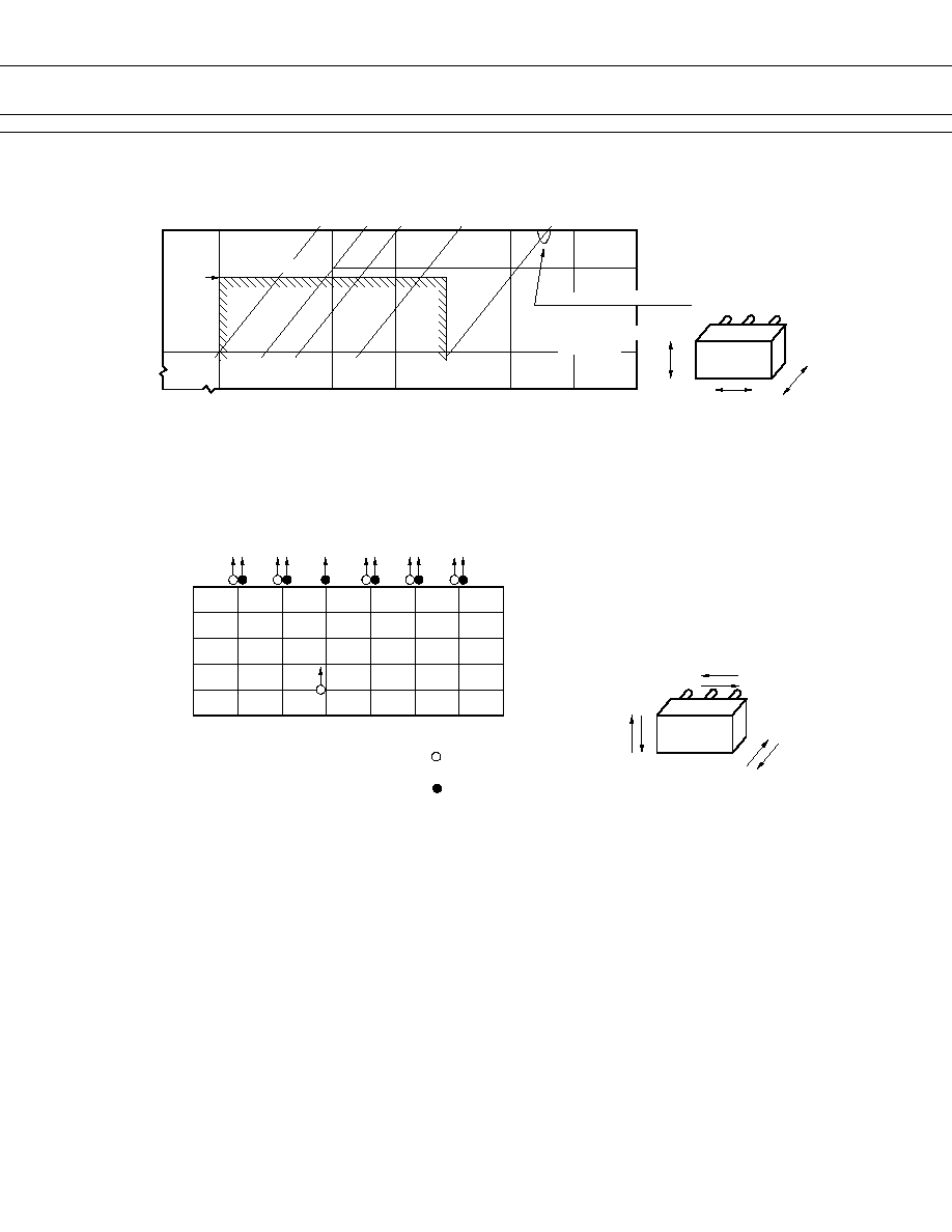
6. SHOCK RESISTANCE CHARACTERISTIC
5. VIBRATION RESISTANCE CHARACTERISTICS
FTR-P5
Y
Z
X
Frequency : 10~2000 Hz
Acceleration : 100 m/s
2
maximum
Vibration direction : see drawing below
Detection level : generation of 1 ms
Acceleration
(m/s
2
)
10
50
100
10
50
100
500
1000
2000
5
1
0.5
0.1
0.01
Dual amplitude (mm)
Frequency (Hz)
Automotive
electronic standard
44 m/s
2
Range where chattering occurs
Break contact
Coil deenergization
on Y-direction
or longer chattering
0
200
400
600
800
1,000
X1
X2
Y1
Y2
Z1
Z2
impact value (m/s
2
)
Impact direction
: Break contact
(coil de-energized)
Impact apply time : 111 ms, half-sine wave
Test condition: coil, energized and de-energized
Impact direction: see drawing below
Detection level : generation of 1ms or longer
FTR-P5
Z2
Z1
Y1
Y2
X2
X1
: Make contact
(coil energized)
contact chattering