s
FEATURES
q
UL, CSA, VDE, SEV, SEMKO, FIMKO, ÷VE, BSI
recognized
q
UL class B (130
∞
C) insulation
q
1 form A (SPST-NO) or 1 form C (SPDT) contact
q
Low profile and space saving--Height: 12.5 mm
--Mounting space: 290 mm
2
q
High sensitivity in small package
--Operating power ............ 0.11 to 0.14 W
--Nominal power ............... 0.22 to 0.29 W
q
High isolation in small package
--Insulation distance : 8 mm
--Dielectric strength : 5,000 VAC (between coil and contacts)
--Surge strength
: 10,000 V
q
Plastic materials --UL 94 flame class V-0
--UL CTI level class 2
q
Plastic sealed type
JS SERIES
POWER RELAY
1 POLE-- 8 A
(MEDIUM LOAD CONTROL)
s
ORDERING INFORMATION
JS ≠ 12
M
E
≠
K
T
≠ (V3)
[Example]
(a) (*) (b) (c) (d)
(e)
(f)
(j)
1
(a)
Series Name
JS : JS Series
(b)
Nominal Voltage
Refer to the COIL DATA CHART
(c)
Contact Arrangement
Nil : 1 form C (SPDT)
M : 1 form A (SPST-NO)
(d)
Contact Material
Nil : Gold plate silver cadmium oxide
E : Silver cadmium oxide
N : Silver tin oxide gold overlay
(e)
Enclosure
K : Plastic sealed type
(f)
Construction
Nil: 3.2 mm
T : 5.0 mm (only JS-MN)
(j)
For low current application
V3 : For low current applications
* not available with "E" contact material
* not available with "T" construction
Note: Actual marking omits the hyphen (-) of (*)
2
JS SERIES
s
SPECIFICATIONS
s
SAFETY STANDARD AND FILE NUMBERS
UL508, 873 (File No. E56140, E108658)
C22.2 No. 14 (File No. LR35579)
VDE 0435, 0631, 0700 (File No. 11039-4940-1010)
Nominal voltage
Contact rating
1/3 HP 125 VAC, 1/2 HP 250 VAC
5 to 60 VDC 10 A
30 VDC/250 VAC, resistive
3A 250 VAC inductive (PF = 0.4)
Pilot duty B 300, C150, Q300
Item
JS
Gold overlay silver alloy (standard)
Gold overlay silver alloy (-V3)
silver alloy
Contact
Arrangement
1 form A (SPST-NO), 1 form C (SPDT)
Material
Gold plate silver cadmium oxide /
cadmium oxide / silver tin oxide gold
overlay
Style
Single
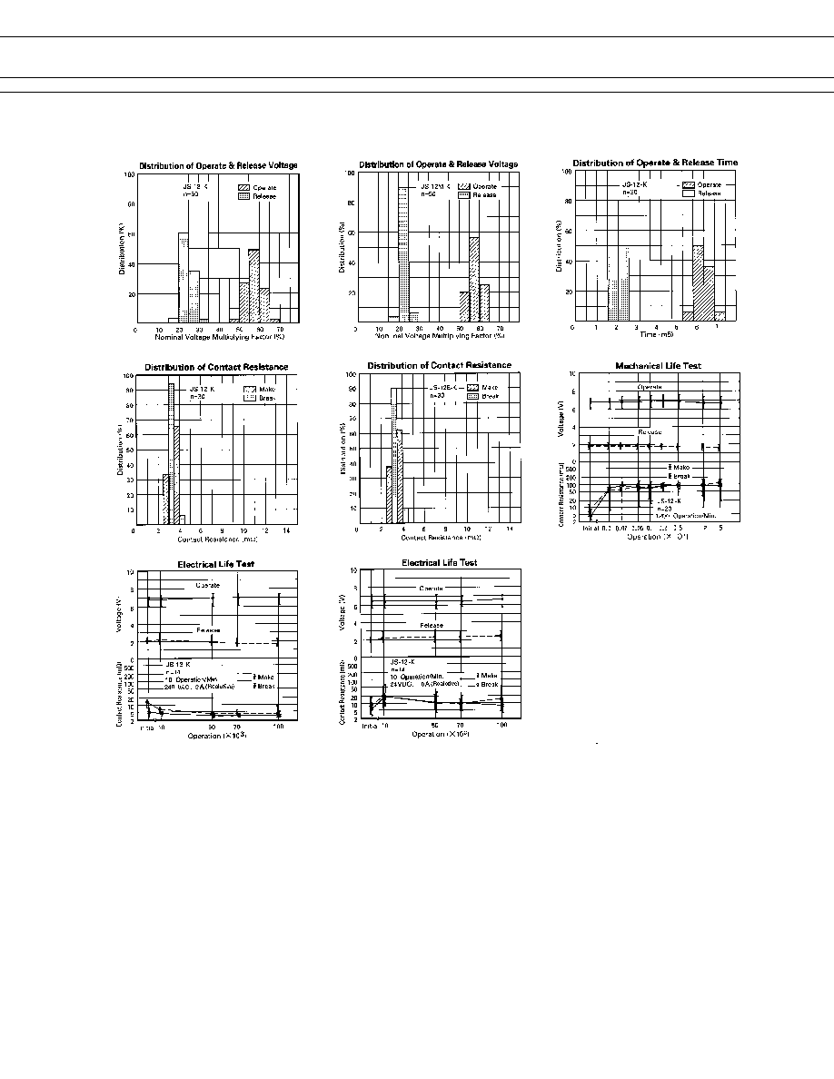
Resistance (initial)
Maximum 30 m
maximum 100 m
(at 1 A 6 VDC)
Rating (resistive)
8 A 250 VAC or 8 A 24 VDC
Maximum Carrying Current
10 A
Maximum Switching Power
2,000 VA, 192 W
Maximum Switching Voltage
400VAC, 250 VDC
Maximum Switching Current
10 A
Minimum Switching Load*
1
10 mA 5 VDC
100 mA 5 VDC
Coil
Nominal Power (at 20
∞
C)
0.22 to 0.29 W
Operate Power (at 20
∞
C)
0.11 to 0.14 W
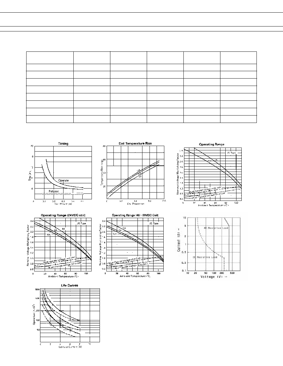
Operating Temperature
≠40
∞
C to +85
∞
C (no frost)
Time Value
Operate (at nominal voltage)
Maximum 10 ms
Release (at nominal voltage)
Maximum 5 ms
Insulation
Resistance (at 500 VDC)
Minimum 1,000 M
Dielectric between open contacts
1,000 VAC 1 minute
Strength between coil and contacts 5,000 VAC 1 minute
Surge Strength
10,000 V (at 1.2
◊
50
µ
s)
Life
Mechanical
2
◊
10
7
operations minimum
Electrical
1
◊
10
5
operations minimum (nominal load)
Other
Vibration Misoperation
10 to 55 Hz (double amplitude of 1.65 mm)
Resistance Endurance
10 to 55 Hz (double amplitude of 3.3 mm)
Shock Misoperation 100 m/s
2
(11
±
1 ms)
Resistance Endurance
1,000 m/s
2
(6
±
1 ms)
Weight
Approximately 8 g
*
1
Minimum switching loads mentioned above are reference values. Please perform the confirmation test with the actual
load before production since reference values may vary according to switching frequencies, environmental conditions
and expected reliability levels.
Gold overlay silver cadmium oxide /
Gold overlay silver tin oxide
5
JS SERIES
0.25
+0.2
1
+0.2
10
±0.3
(1.19)
(2.1)
0.8
+0.2
3
.
3
+0.
4
-
0.2
1
2.5
+0.
3
0.4
+0.2
0.2
+0.2
18.9
±0.25
29
±0.3
5
±0.2
Soldering
7.62
±0.2
s
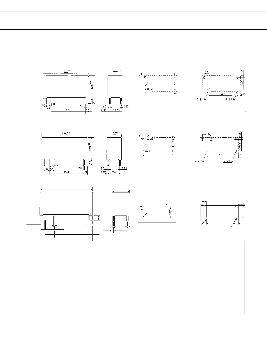
DIMENSIONS
q
Dimensions
q
Schematics
(BOTTOM VIEW)
q
PC board mounting
hole layout
(BOTTOM VIEW)
JS-MK type
JS-K type
Unit: mm
JS-MN-KT type
COM
5
1
3
4
NO
3 -¯ .5
±
0.1
5
±
0.1
2 -¯ 1.3
±
0.1
18.9
±
0.1
7.62
±
0.1
(1.19)
(2.1)
© 2003 Fujitsu Components America, Inc. All company and product names are trademarks or registered trademarks
of their respective owners. Rev. 06/03/2003
Japan
Fujitsu Component Limited
Gotanda-Chuo Building
3-5, Higashigotanda 2-chome, Shinagawa-ku
Tokyo 141, Japan
Tel: (81-3) 5449-7010
Fax: (81-3) 5449-2626
Email: promothq@ft.ed.fujitsu.com
Web: www.fcl.fujitsu.com
North and South America
Fujitsu Components America, Inc.
250 E. Caribbean Drive
Sunnyvale, CA 94089 U.S.A.
Tel: (1-408) 745-4900
Fax: (1-408) 745-4970
Email: marcom@fcai.fujitsu.com
Web: www.fcai.fujitsu.com
Europe
Fujitsu Components Europe B.V.
Diamantlaan 25
2132 WV Hoofddorp
Netherlands
Tel: (31-23) 5560910
Fax: (31-23) 5560950
Email: info@fceu.fujitsu.com
Web: www.fceu.fujitsu.com
Asia Pacific
Fujitsu Components Asia Ltd.
102E Pasir Panjang Road
#04-01 Citilink Warehouse Complex
Singapore 118529
Tel: (65) 6375-8560
Fax: (65) 6273-3021
Email: fcal@fcal.fujitsu.com
www.fcal.fujitsu.com
Fujitsu Components
International
Headquarter
Offices