
s
FEATURES
q
UL, CSA, VDE recognized
q
High sensitivity and low power consumption
q
High isolation
q
Wide operating range
q
DIL pitch terminals
q
Plastic sealed type
q
Socket mounting type and socket available
q
Compatible with solid state relays type SJ (see page
365, 366) in size and pin (terminal) arrangement
(a)
Series Name
JY : JY Series
(b)
Nominal Voltage
Refer to the COIL DATA CHART
Nil : 3 A (Single contact)
(c)
Contact Style
H : 5 A (Single contact)
W : 3A (Bifurcated contact)
Nil : Gold-plate silver cadmium oxide (single type)
(d)
Contact Material
Nil : Gold overlay silver alloy (bifurcated)
E : Silver cadmium oxide (single type)
(e)
Enclosure
K : Plastic sealed type
(f )
Terminal Classification
Nil : PC board mounting type
P : Socket mounting type (without JY-W)
Note: 1. Actual marking omits the hyphen (-) of (*)
2. Actual marking omits the P of (*
2
)
s
ORDERING INFORMATION
JY ≠ 12
H
E
≠
K
P*
2
[Example]
(a) (*) (b) (c) (d)
(e)
(f )
JY SERIES
POWER RELAY
1 POLE-- 3, 5 A
(MEDIUM LOAD CONTROL)
s
SAFETY STANDARD AND FILE NUMBERS
UL508 (FIle No. E56140)
C22.2 No. 14 (File No. LR35579)
VDE 0435 (File No. 11039-4940-1014)
Please request when the approval markings are required on the cover and/or relay recognized by SEV is required.
Type
Nominal voltage
Contact rating
1/8 HP 125 VAC/ 250 VAC
JY-H, JY-HE
4.5 to 48 VDC
5 A 30 VDC/250 VAC, resistive
Pilot duty C 150
1/10 HP 125 VAC/ 250 VAC
JY, JY-W, JY-E
4.5 to 48 VDC
3 A 30 VDC/250 VAC, resistive
Pilot duty D 150
1
2
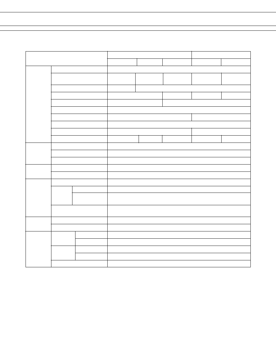
JY SERIES
3 A Type
5 A Type
Item
JY-( ) W-K
JY-( ) -K
JY-( ) E-K
JY-( ) H-K
JY-( ) HE-K
Contact
Arrangement
1 form A (SPST-NO)
Material
Style
Bifurcated Single
Resistance (initial) (at 1A 6 VDC)
Rating (resistive)
Maximum Carrying Current
5 A
Maximum Switching Power
750 VA, 90 W
1,250 VA, 150 W
Maximum Switching Voltage
250 VAC, 150 VDC
Maximum Switching Current
3 A
5 A
Minimum Switching Load*
1
0.1 mA 100 mVDC 10 mA 5 VDC 100 mA 5 VDC 10 mA 5 VDC 100 mA 5 VDC
Coil
Nominal Power (at 20
∞
C)
0.2 W (48 V type: 0.36 W)
Operate Power (at 20
∞
C)
0.1 W (48 V type: 0.17 W)
Operating Temperature
≠40
∞
C to +90
∞
C (no frost) (48V type: +80
∞
C)
Time Value
Operate (at nominal voltage)
Maximum 6 ms
Release (at nominal voltage)
Maximum 3 ms
Insulation
Resistance (at 500 VDC)
Minimum 1,000 M
between open contacts
750 VAC 1 minute
Dielectric
between coil and contacts
Standard type 2,000 VAC 1 minute
High dielectric strength type 3,000 VAC 1 minute
Surge Strength
Standard type 4,000 V (at 1.2
◊
50
µ
s)
High dielectric strength type 5,000 V (at 1.2
◊
50
µ
s)
Life
Mechanical
2
◊
10
7
operations minimum
Electrical
1
◊
10
5
operations minimum (contact rating)
Other
Vibration Misoperation
10 to 55 Hz (double amplitude of 1.5 mm)
Resistance Endurance
10 to 55 Hz (double amplitude of 4.5 mm)
Shock Misoperation
100 m/s
2
(11
±
1 ms)
Resistance Endurance
1,000 m/s
2
(6
±
1 ms)
Weight
Approximately 5 g
Gold-plate
silver cadmium
oxide
s
SPECIFICATIONS
*
1
Minimum switching loads mentioned above are reference values. Please perform the confirmation test with the actual load
before production since reference values may vary according to switching frequencies, environmental conditions and
expected reliability levels.
Gold-overlay
silver alloy
silver cadmium
oxide
Maximum 30 m
Max. 100 m
Max. 30 m
Max. 100 m
3 A 250 VAC or 3 A 30 VDC
5 A 250 VAC or 5 A 30 VDC
Gold-plate
silver cadmium
oxide
silver cadmium
oxide

3
JY SERIES
MODEL
Nominal Coil resistance
Must operate
Must release
Nominal
5 A Type
3 A Type
voltage
(
±
10%)
voltage*
1
voltage*
1
power
JY-( ) H, JY-( ) HE
JY-( ), JY-( ) W, JY-( )E
JY- 4.5 H ( )-K
JY- 4.5 ( )-K
4.5 VDC
100
3.1 VDC
0.23 VDC
200 mW
JY- 5 H ( )-K
JY- 5 ( )-K
5 VDC
125
3.5 VDC
0.25 VDC
200 mW
JY- 6 H ( )-K
JY- 6 ( )-K
6 VDC
180
4.2 VDC
0.3 VDC
200 mW
JY- 9 H ( )-K
JY- 9 ( )-K
9 VDC
405
6.3 VDC
0.45 VDC
200 mW
JY- 12 H ( )-K
JY- 12 ( )-K
12 VDC
720
8.4 VDC
0.6 VDC
200 mW
JY- 18 H ( )-K
JY- 18 ( )-K
18 VDC
1,620
12.6 VDC
0.9 VDC
200 mW
JY- 24 H ( )-K
JY- 24 ( )-K
24 VDC
2,880
16.8 VDC
1.2 VDC
200 mW
JY- 48 H ( )-K
JY- 48 ( )-K
48 VDC
6,400
32.6 VDC
2.4 VDC
360 mW
JY-101-K
23.5 VDC
2,760
15.5 VDC
1.18 VDC
200 mW
JY-105-K
12 VDC
720
8.4 VDC
0.6 VDC
200 mW
JY-107-K
5 VDC
125
3.5 VDC
0.25 VDC
200 mW
Note: *
1
Specified values are subject to pulse wave voltage.
All values in the table are measured at 20
∞
C.
s
COIL DATA CHART
s
CHARACTERISTIC DATA

