 | –≠–ª–µ–∫—Ç—Ä–æ–Ω–Ω—ã–π –∫–æ–º–ø–æ–Ω–µ–Ω—Ç: LZG-W | –°–∫–∞—á–∞—Ç—å:  PDF PDF  ZIP ZIP |
s
ORDERING INFORMATION
LZG ≠
B
12
H
M
S
E
≠
K
[Example]
(a)
(b)
(c)
(d)
(e)
(f )
(g)
(h)
s
FEATURES
q
UL (UL372, UL508, UL873), CSA, VDE
q
4 kinds of contact ratings
--Low level to 10 amps switching
q
Standard and high sensitivity types available
q
High isolation in small package
--Dielectric strength: 2,500 VAC
(between coil and contacts)
--Surge strength: 7,000 V
q
UL class B (130
∞
C) insulation type available
(only plastic sealed type)
q
Plastic sealed type
q
Printed circuit terminals compatible with LZ relay
q
Environmentally friendly cadmium free contact type is
available.
(a)
Series Name
LZG: LZG Series
(b)
Coil Heat Proof Class
Nil : Standard type
B
: UL Class B insulation type (130
∞
C)
(c)
Nominal Voltage
Refer to the COIL DATA CHART
(d)
Contact Rating
Nil : 3 A
H
: 5 A
V
: 10 A (only LZG-M)
W
: 1 A (bifurcated)
(e)
Contact Arrangement
Nil : 1 form C (SPDT)
M
: 1 form A (SPST-NO)
( f )
Coil Type
Nil : Standard type
S
: High sensitivity type (without LZG-V)
(g)
Contact Material (Rating)
Nil : Gold overlay silver-palladium (only LZG-W)
Nil : Gold overlay silver-nickel (3 A, 5 A)
Nil : Silver alloy (10 A) (only LZG-VM)
E
: Silver-nickel (3 A, 5 A)
(h)
Enclosure
Nil : Flux free type
K
: Plastic sealed type (only LZG-B)
C
: Plastic sealed type (with tape) (only LZG-B)
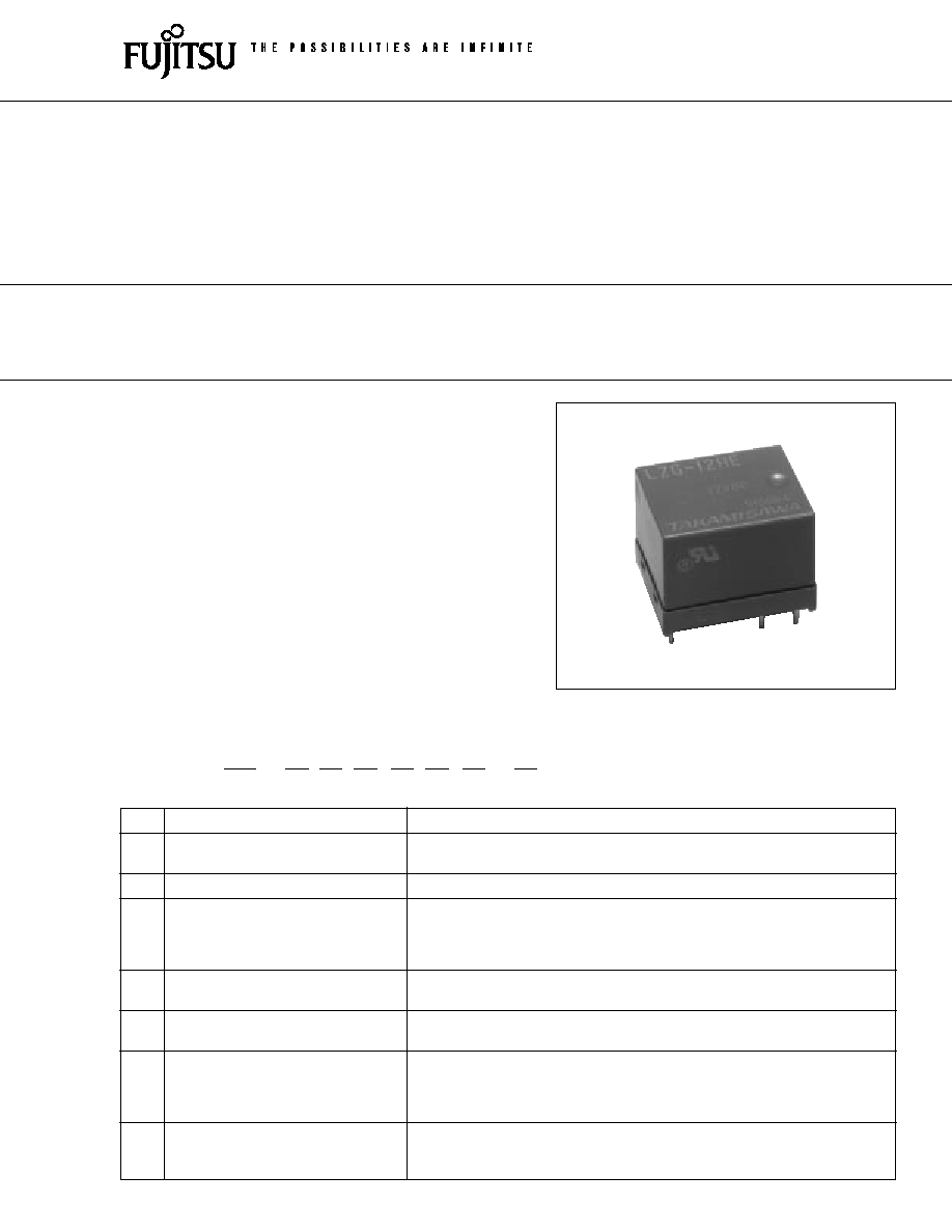
LZG SERIES
POWER RELAY
1 POLE-- 1, 3, 5, 10 A
(CADMIUM FREE CONTACTS TYPE)
1
2
LZG SERIES
s
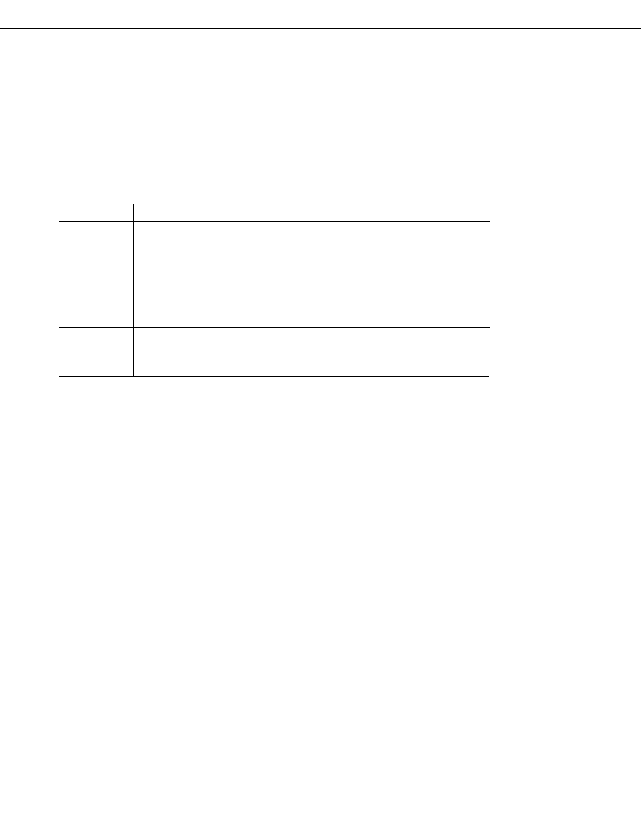
SAFETY STANDARD AND FILE NUMBERS
UL372, 508, 873 (File No. E56140)
C 22.2 No. 14 (File No. LR35579)
VDE 0435 (File No. 11039-4940-1004)
Please note that UL/CSA/VDE ratings may differ from the standard ratings. Only "NIL" and "H" contacts have VDE
approval.
Please request when the approval markings are required on the cover and/or relay recognized by SEV is required.
Type
Nominal voltage
Contact rating
LZG- ( )
1.5 to 48 VDC
1/10 HP 120 VAC/240 VAC
LZG- ( )S
1.5 to 24 VDC
2.5 A 240 VAC resistive
3 A 30 VDC/120 VAC resistive
Pilot duty D 150
LZG- ( )H
1.5 to 48 VDC
1/8 HP 120 VAC/240 VAC
LZG- ( )HS
1.5 to 24 VDC
4 A 240 VAC resistive
5 A 30 VDC/120 VAC resistive
1 A 250VAC inductive
Pilot duty C 150
LZG- ( )VM
1.5 to 48 VDC
1/4 HP 120 VAC/240 VAC
7 A 240 VAC resistive
10 A 24 VDC/120 VAC resistive
Pilot duty C 150
3
LZG SERIES
s
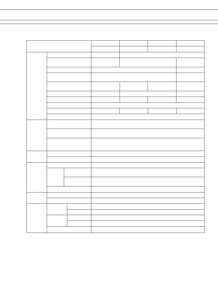
SPECIFICATIONS
10 A Type
5 A Type
3 A Type
1 A Type
Item
LZG-( )VM
LZG-( )H, LZG-( )HE LZG( ), LZG-( )E
LZG-( )W
Contact
Arrangement 1 form A (SPST-NO)
1 form A (SPST-NO) or 1 form C (SPDT)
Material
Silver alloy
Style
Single
Bifurcated
Resistance (initial) (at 1 A 6 VDC)
Maximum 70 m
(LZG-H)
Maximum 100 m
(LZG-VM, HE, E)
Rating (resistive) 10 A 120 VAC/24 VDC 5 A 120 VAC/24 VDC 3 A 120 VAC/30 VDC 1 A 120 VAC/30 VDC
1/4 HP 120 VAC 1/8 HP 120 VAC 1/10 HP 120 VAC
Maximum Carrying Current
10 A 5 A
1 A
Maximum Switching Power
Maximum Switching Voltage
250 VAC, 150 VDC
Maximum Switching Current
10 A 5 A
3 A 1 A
Minimum Switching Load*
1
10 mA 5 VDC (LZG-H) 100 mA 5 VDC (LZG-VM, HE, E) 0.1 mA 100 VDC
Coil
Nominal Power (at 20
∞
C)
Standard type: 0.45 to 0.6 W
High sensitivity type: 0.33 W
Operate Power (at 20
∞
C)
Standard type: 0.17 to 0.22 W
High sensitivity type: 0.14 W
Operating Temperature
Standard type: ≠30
∞
C to +70
∞
C (no frost)
High sensitivity type: ≠30
∞
C to +80
∞
C (no frost)
(refer to the CHARACTERISTIC DATA)
Time Value
Operate (at nominal voltage)
Maximum 7 ms
Release (at nominal voltage)
Maximum 4 ms
Insulation
Resistance (at 500 VDC)
Minimum 250 M
between
750 VAC 1 minute
Dielectric open contacts
Strength
between coil
2,500 VAC 1 minute
and contacts
Surge Strength
7,000 V (at 1.2
◊
50
µ
s)
Life
Mechanical 2
◊
10
7
operations minimum
Electrical
1
◊
10
5
operations minimum (rated load)
Other
Vibration Misoperation
10 to 55 Hz (double amplitude of 3.3 mm)
Resistance
Endurance
10 to 55 Hz (double amplitude of 3.3 mm)
Shock Misoperation
100 m/s
2
(11
±
1 ms)
Resistance
Endurance
1,000 m/s
2
(6
±
1 ms)
Weight
Approximately 9.2 g
*
1
Minimum switching loads mentioned above are reference values. Please perform the confirmation test with the actual
load before production since reference values may vary according to switching frequencies, environmental conditions
and expected reliability levels.
Gold overlay silver alloy
Gold overlay
silver-palladium
1,680 VA, 240 W
960 VA, 120 W
600 VA, 90 W
190 VA, 30 W
Max. 50 m
4
LZG SERIES
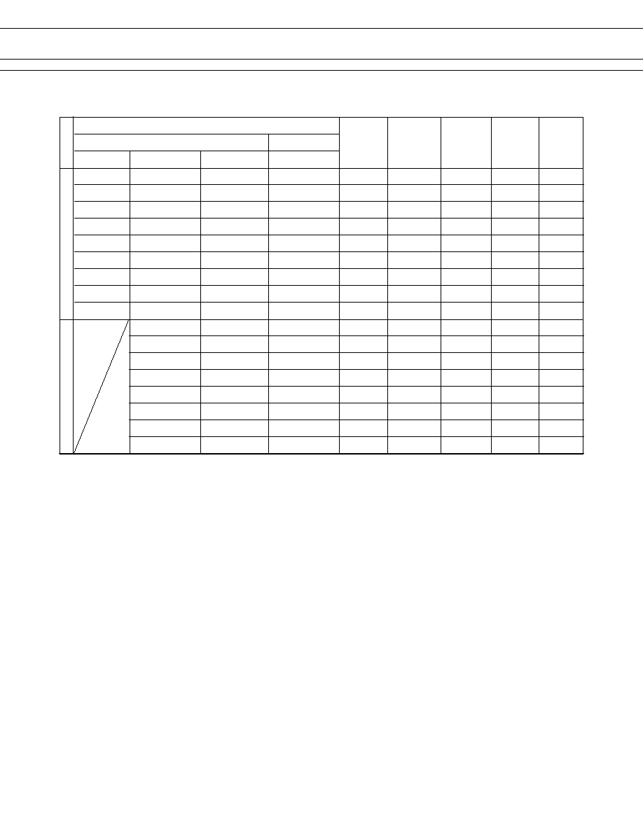
s
COIL DATA CHART
MODEL
Nominal
Coil
Must
Must
Nominal
Single
Bifurcated
resistance
operate
release
voltage
(
±
10%)
voltage
voltage
power
10 A Type
5 A Type
3 A Type
1 A Type
LZG-(B) 1.5 VM LZG-(B) 1.5H (M) (E) LZG-(B) 1.5 (M) (E) LZG-(B) 1.5 W (M)
1.5 VDC
5
0.97 VDC
0.08 VDC
450 mW
LZG-(B) 3 VM LZG-(B) 3H (M) (E) LZG-(B) 3 (M) (E) LZG-(B) 3 W (M)
3 VDC
20
1.95 VDC
0.15 VDC
450 mW
LZG-(B) 5 VM LZG-(B) 5H (M) (E) LZG-(B) 5 (M) (E) LZG-(B) 5 W (M)
5 VDC
56
3.25 VDC
0.25 VDC
450 mW
LZG-(B) 6 VM LZG-(B) 6H (M) (E) LZG-(B) 6 (M) (E) LZG-(B) 6 W (M)
6 VDC
80
3.9 VDC
0.3 VDC
450 mW
LZG-(B) 9 VM LZG-(B) 9H (M) (E) LZG-(B) 9 (M) (E) LZG-(B) 9 W (M)
9 VDC
180
5.85 VDC
0.45 VDC
450 mW
LZG-(B) 12 VM LZG-(B) 12H (M) (E) LZG-(B) 12 (M) (E) LZG-(B) 12 W (M)
12 VDC
320
7.8 VDC
0.6 VDC
450 mW
LZG-(B) 18 VM LZG-(B) 18H (M) (E) LZG-(B) 18 (M) (E) LZG-(B) 18 W (M)
18 VDC
720
11.7 VDC
0.9 VDC
450 mW
LZG-(B) 24 VM LZG-(B) 24H (M) (E) LZG-(B) 24 (M) (E) LZG-(B) 24 W (M)
24 VDC
1,280
15.6 VDC
1.2 VDC
450 mW
LZG-(B) 48 VM LZG-(B) 48H (M) (E) LZG-(B) 48 (M) (E) LZG-(B) 48 W (M)
48 VDC
3,800
28.8 VDC
2.4 VDC
600 mW
LZG-(B) 1.5H (M)S (E) LZG-(B) 1.5 (M)S (E) LZG-(B) 1.5 W (M) S
1.5 VDC
6.8
0.97 VDC
0.08 VDC
330 mW
LZG-(B) 3H (M)S (E)
LZG-(B) 3 (M)S (E) LZG-(B) 3 W (M) S
3 VDC
27
1.95 VDC
0.15 VDC
330 mW
LZG-(B) 5H (M)S (E)
LZG-(B) 5 (M)S (E) LZG-(B) 5 W (M) S
5 VDC
80
3.25 VDC
0.25 VDC
330 mW
LZG-(B) 6H (M)S (E)
LZG-(B) 6 (M)S (E) LGZ-(B) 6 W (M) S
6 VDC
110
3.9 VDC
0.3 VDC
330 mW
LZG-(B) 9H (M)S (E)
LZG-(B) 9 (M)S (E) LZG-(B) 9 W (M) S
9 VDC
250
5.85 VDC
0.45 VDC
330 mW
LZG-(B) 12H (M)S (E)
LZG-(B) 12 (M)S (E) LZG-(B) 12 W (M) S
12 VDC
440
7.8 VDC
0.6 VDC
330 mW
LZG-(B) 18H (M)S (E)
LZG-(B) 18 (M)S (E) LZG-(B) 18 W (M) S
18 VDC
990
11.7 VDC
0.9 VDC
330 mW
LZG-(B) 24H (M)S (E)
LZG-(B) 24 (M)S (E) LZG-(B) 24 W (M) S
24 VDC
1,780
15.6 VDC
1.2 VDC
330 mW
High Sensitivity
T
ype
Standard
T
ype
Note: All values in the table are measured at 20
∞
C.
5
LZG SERIES
s
CHARACTERISTIC AND REFERENCE DATA
Please see LZ relays.
s
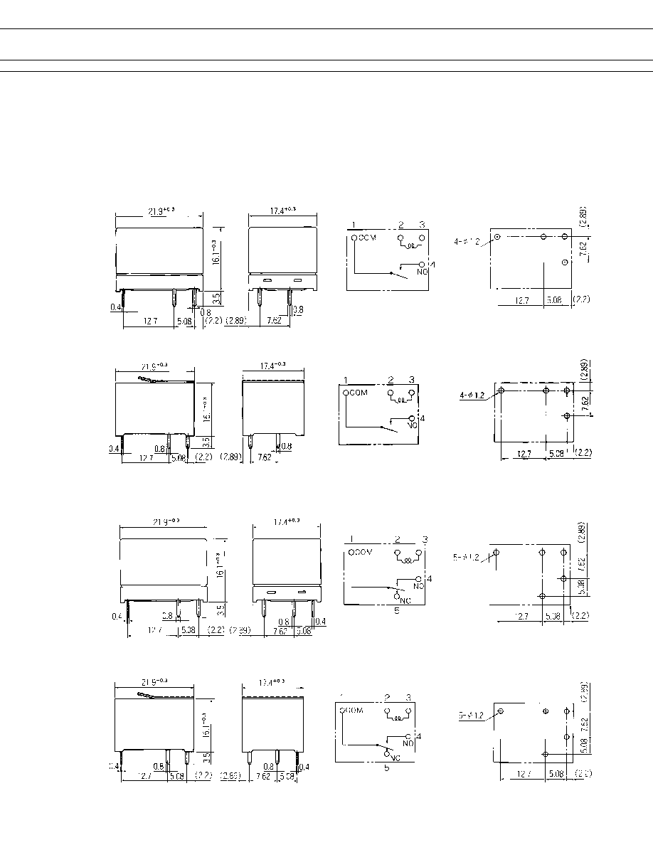
DIMENSIONS
q
Dimensions
q
Schematics
(BOTTOM VIEW)
q
PC board mounting
hole layout
(BOTTOM VIEW)
LZG-M type
LZG-M-K, LZG-M-C type (Plastic sealed type)
Dotted line : Seal tape (LZG-M-C Type)
LZG type
LZG-K, LZG-C type (Plastic sealed type)
Dotted line : Seal tape (LZG-C type)
Unit: mm