1
DS04-27300-2E
FUJITSU SEMICONDUCTOR
DATA SHEET
--
ASSP
VOLTAGE DETECTOR
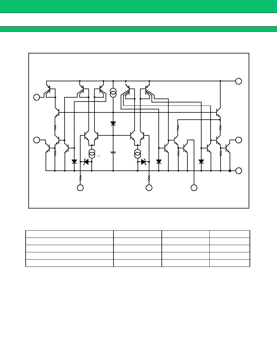
MB3761
VOLTAGE DETECTOR
Designed for voltage detector applications, the Fujitsu MB3761 is a dual
comparator with a built-in high precision reference voltage generator.
Outputs are open-collector outputs and enable use of the OR-connection
between both channels. Both channels have hysteresis control outputs.
Because of a wide power supply voltage range and a low power supply
current, the MB3761 is suitable for power supply monitors and battery
backup systems.
∑ Wide power supply voltage range: 2.5 V to 40 V
∑ Low power and small voltage dependency supply current: 250
µ
A
typical.
∑ Built-in stable low voltage generator: 1.20 V typical.
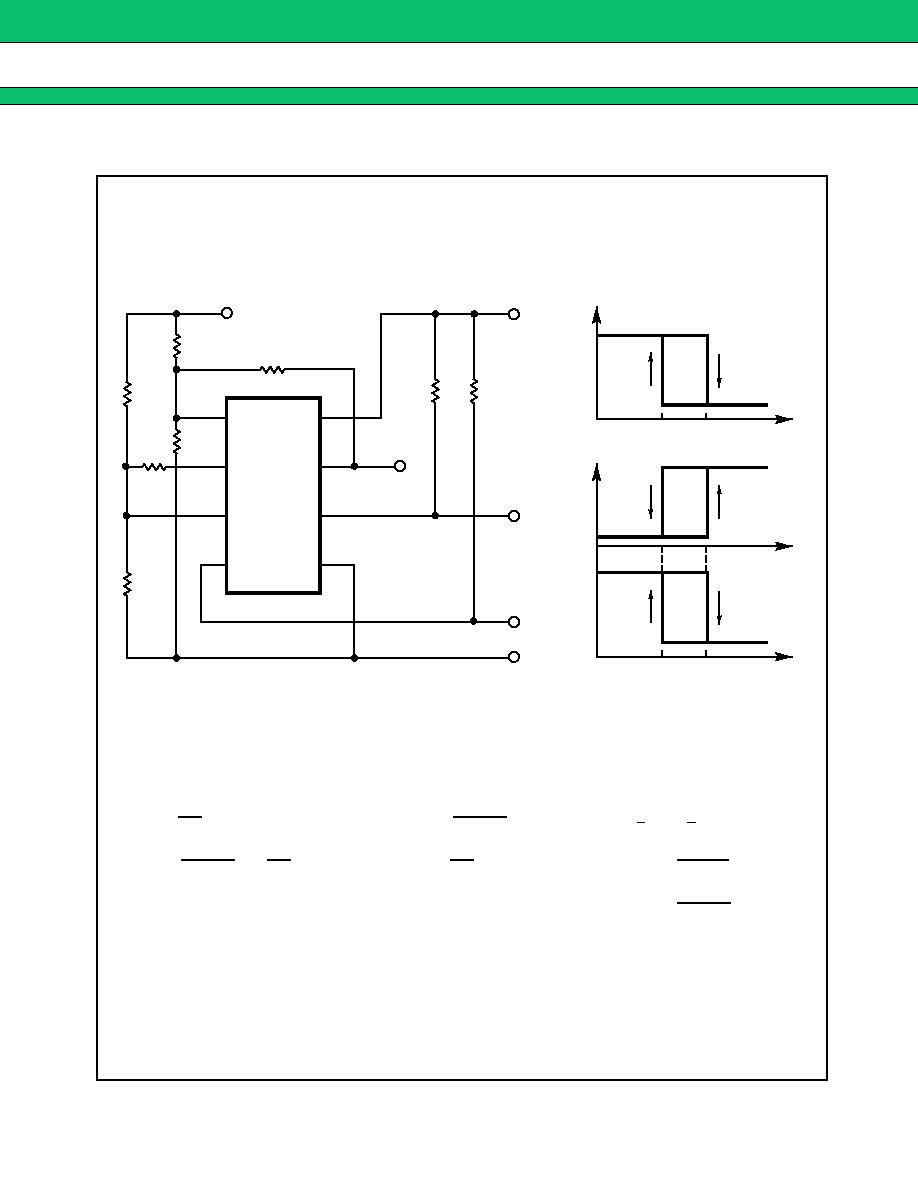
∑ Easy-to-add hysteresis characteristics.
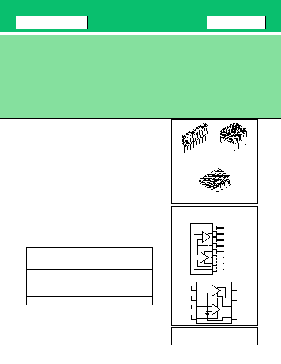
∑ Package: 8-pin Plastic SIP Package (Suffix: -PS)
8-pin Plastic DIP Package (Suffix: -P)
8-pin Plastic FPT Package (Suffix: -PF)
ABSOLUTE MAXIMUM RATINGS (See NOTE)
Rating
Symbol
Value
Unit
Power Supply Voltage
V
CC
41
V
Output Voltage
V
O
41
V
Output Current
I
O
50
mA
Input Voltage
V
IN
-0.3 to +6.5
V
Power Dissipation
P
D
350
(TA
70
∞
C)
mW
Storage Temperature
T
STG
-55 to 125
∞
C
NOTE: Permanent device damage may occur if ABSOLUTE MAXI-
MUM RATINGS are exceeded. Functional operation should be
restricted to the conditions as detailed in the operational sections
of this data sheet. Exposure to absolute maximum rating conditions
for extended periods may affect device reliability.
PIN ASSIGNMENT
V
HYS-B
OUT-B
GND
OUT-A
IN-A
HYS-A
IN-B
CC
V
HYS-B
OUT-B
GND
OUT-A
IN-A
HYS-A
IN-B
CC
8
7
6
5
4
3
2
1
8
7
6
5
4
3
2
1
(FRONT VIEW)
(TOP VIEW)
B
A
(+)
(--)
+
(+)
(--)
+
--
+
--
B
+
--
A
(+)
(--)
(+)
(--)
PLASTIC PACKAGE
SIP-08P-M03
PLASTIC PACKAGE
DIP-08P-M01
PLASTIC PACKAGE
FPT-08P-M01
This device contains circuitry to protect the inputs against damage due
to high static voltages or electric fields. However, it is advised that
normal precautions be taken to avoid application of any voltage
higher than maximum rated voltages to this high impedance circuit.
3
MB3761
s
s
s
s
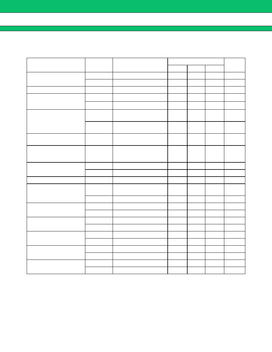
ELECTRICAL CHARACTERISTICS
T
A
=25
∞
C, V
CC
=5V
Parameter
Designator
Conditions
Values
Unit
Min
Typ
Max
Power Supply Voltage
I
CCL
V
CC
=40 V, V
IL
=1.0 V
-
250
400
µ
A
I
CCH
V
CC
=40 V, V
IH
=1.5 V
-
400
600
µ
A
Threshold Voltage
V
TH
I
O
=2 mA, V
O
=1 V
1.15
1.20
1.25
V
Deviation of Threshold Volt-
age
V
TH1
2.5 V
V
CC
5.5 V
-
3
12
mV
V
TH2
4.5 V
V
CC
40 V
-
10
40
mV
Offset Voltage between Out-
puts
V
OOSA
I
OA
= 4.5 mA, V
OA
=2 V
I
HA
= 20
m
A, V
HA
=3 V
-
2.0
-
mV
V
OSSB
I
OB
=3 mA, V
OB
=2 V
I
HB
=3 mA, V
HB
=2 V
-
2.0
-
mV
Temperature Coefficient of
Threshold Voltage
-20
∞
C
T
A
70
∞
C
-
±
0.05
-
mV/
∞
C
Difference Voltage on
Threshold Voltage between
Channel
V
THAB
-10
-
-10
mV
Input Current
I
IL
V
IL
=1.0 V
-
5
nA
I
IH
V
IH
=1.5 V
-
100
500
nA
Output Leakage Current
I
OH
V
O
=40 V, V
IL
=1.0 V
-
-
1
µ
A
Hysteresis Output Leakage
Current
I
HLA
V
CC
=40 V, V
HA
=0 V,
V
IL
=1.0 V
-
-
0.1
µ
A
I
HHB
V
HB
=40 V, V
IH
=1.5 V
-
-
1
µ
A
Output Sink Current
I
OLA
V
O
=1.0 V, V
IH
=1.5 V
6
12
-
mA
I
OLB
V
O
=1.0 V, V
IH
=1.5 V
4
10
-
mA
Hysteresis Current
I
HHA
V
H
=0 V, V
IH
=1.5 V
40
80
-
µ
A
I
HLB
V
H
=1.0 V,V
IL
=1.0 V
4
10
-
mA
Output Saturation Voltage
V
OLA
I
O
= 4.5 mA, V
IH
=1.5 V
-
120
400
mV
V
OLB
I
O
= 3.0 mA, V
IH
=1.5 V
-
120
400
mV
Hysteresis Saturation
V
HHA
I
H
= 20
µ
A, V
IH
=1.5 V
-
50
200
mV
V
HLB
I
H
= 3.0 mA, V
IL
=1.0 V
-
120
400
mV
Output Delay Time
t
PHL
R
L
=5 K
-
2
-
µ
s
t
PLH
R
L
=5 K
-
3
-
µ
s
5
MB3761
s
s
s
s
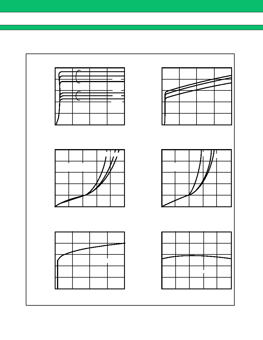
TYPICAL PERFORMANCE CHARACTERISTICS
Output (B) Current I
OLB
(mA)
Power Supply Voltage V
CC
(V)
Power Supply Voltage V
CC
(V)
Temperature T
A
(
∞
C)
Power Supply Voltage V
CC
(V)
Output (A) Current I
OLA
(mA)
I
HHA
( µA)
-20
∞
C
70
∞
C
V
CC
=5V
V
CC
=5V
V
IH
=1.5V
25
∞
C
V
CC
=5V
V
IH
=1.5V
1.0
0
Output
V
OLA
(V)
0.8
0.6
0.4
0.2
0
5
10
15
20
1.0
0.8
0.6
0.4
0.2
0
(A)
Voltage
25
Output
V
OLB
(V)
(B)
Voltage
1.22
Threshold
V
TH
(V)
1.21
1.20
1.19
1.18
1.17
Voltage
0
10
20
30
40
1.22
Threshold
V
TH
(V)
1.21
1.20
1.19
1.18
1.17
Voltage
-20
0
20
40
60
80
0
5
10
15
20
25
-20
∞
C
Fig. 6 -
Output (B) Voltage
vs. Output (B) Current
Fig. 7 - Threshold Voltage
vs. Power Supply Voltage
Fig. 8 -
Threshold Voltage
vs. Temperature
25
∞
C
70
∞
C
Fig. 5 - Output (A) Voltage
vs. Output (A) Current
TA=25
∞
C
500
0
Power
Supply
Current
400
300
200
100
0
10
20
30
40
150
0
Hysteresis
Current
120
90
60
30
0
10
20
30
40
Fig. 3 - Power Supply Current
vs Power Supply Voltage
Fig. 4 -
Hysteresis (A) Current
vs Power Supply Voltage
70
∞
C
25
∞
C
70
∞
C
70
∞
C
25
∞
C
-20
∞
C
-20
∞
C
-20
∞
C
25
∞
C
V
IH
=1.5V
V
IH
= 1.5V
V
IL
=1.0V
(A)
I
CC
(µA)