DS04-27201-3E
FUJITSU SEMICONDUCTOR
DATA SHEET
ASSP For Power Supply Applications
Switching Regulator Controller
MB3776A
s
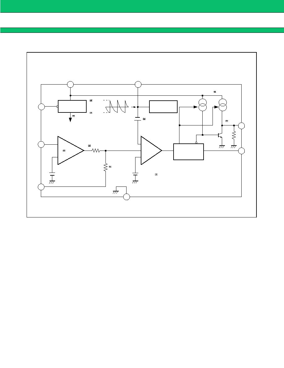
DESCRIPTION
MB3776A is a PWM system switching regulator controller. Because of its low operating supply voltage and power-
down, the MB3776A is ideal for use in DC/DC converters for battery-powered portable equipment.
s
FEATURES
∑ Wide supply voltage range: (2 V to 15 V)
∑ Wide oscillation frequency range, high-frequency oscillation: (10 kHz to 500 kHz)
∑ Push-pull output. Drive current set with external resistor
∑ Bulit-in idle period circuit
∑ Internally set error amplifier gain, few external components
∑ Bulit-in power-down function
s
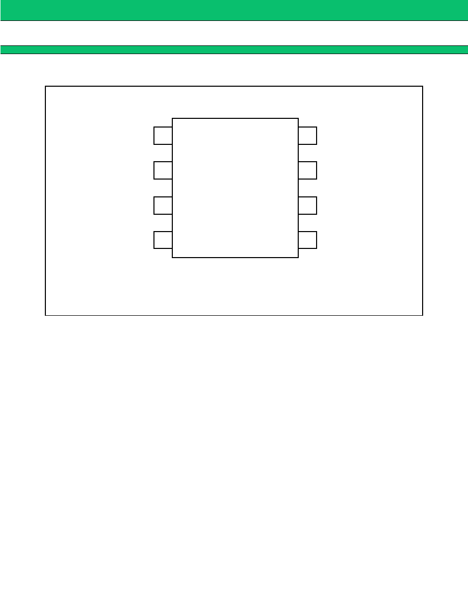
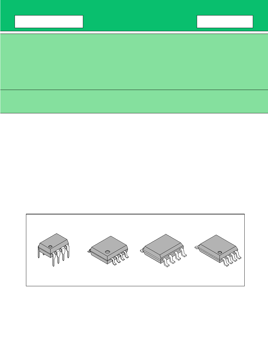
PACKAGES
8-pin Plastic DIP
(DIP-8P-M01)
8-pin Plastic SOP
(FPT-8P-M01)
8-pin Plastic SOL
(FPT-8P-M02)
8-pin Plastic SSOP
(FPT-8P-M03)
4
MB3776A
s
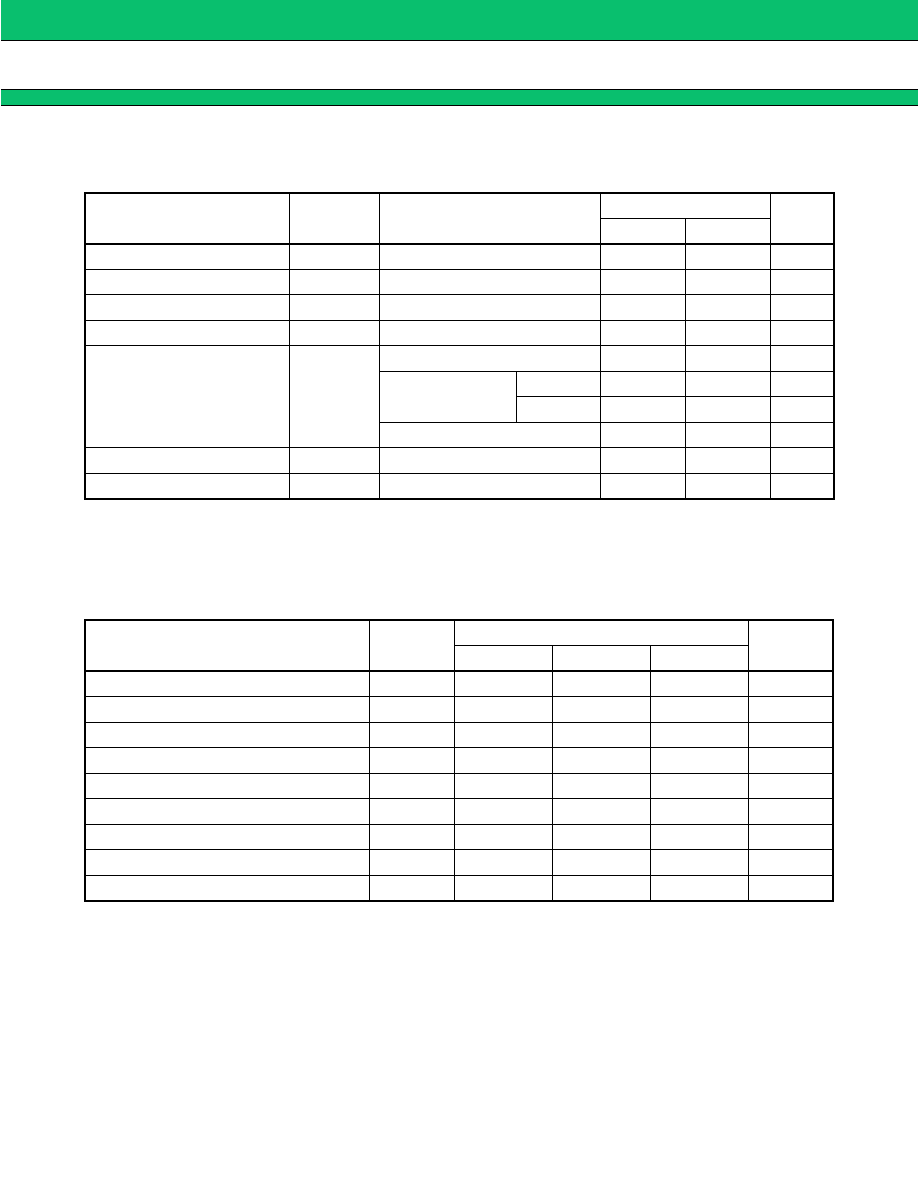
ABSOLUTE MAXIMUM RATINGS
(Ta = +25
∞
C)
* : The packages are mounted on the epoxy board (10 cm
◊
10 cm
◊
1.5 mm)
WARNING: Semiconductor devices can be permanently damaged by application of stress (voltage, current,
temperature, etc.) in excess of absolute maximum ratings. Do not exceed these ratings.
s
RECOMMENDED OPERATING CONDITIONS
WARNING: Recommended operating conditions are normal operating ranges for the semiconductor device. All
the device's electrical characteristics are warranted when operated within these ranges.
Always use semiconductor devices within the recommended operating conditions. Operation outside
these ranges may adversely affect reliability and could result in device failure.
No warranty is made with respect to uses, operating conditions, or combinations not represented on
the data sheet. Users considering application outside the listed conditions are advised to contact their
FUJITSU representative beforehand.
Parameter
Symbol
Condition
Rating
Unit
Min.
Max.
Power supply voltage
V
CC
--
--
16
V
Error amp. input voltage
V
I
--
≠0.3
+10
V
Output source current
I
SOURCE
--
--
≠50
mA
Output sink current
I
SINK
--
--
50
mA
Power dissipation
P
D
Ta
+25
∞
C (DIP)
--
550
mW
Ta
+25
∞
C (SOP)
EIAJ
--
*570
mW
JEDEC
--
*430
mW
Ta
<
+25
∞
C (SSOP)
--
*580
mW
Operating temperature
Top
--
≠30
+75
∞
C
Storage temperature
Tstg
--
≠55
+125
∞
C
Parameter
Symbol
Value
Unit
Min.
Typ.
Max.
Power supply voltage
V
CC
2.0
--
15
V
Error amp. input voltage
V
I
≠0.2
--
1.0
V
Output source current
I
SOURCE
≠40
--
--
mA
Output sink current
I
SINK
--
--
40
mA
Phase compensation capacitor
C
P
--
0.1
--
µ
F
Timing capacitor
C
T
100
1000
10000
pF
Timing resistor
R
T
1.0
3.0
5.0
k
Oscillator frequency
f
OSC
10
200
500
kHz
Operating temperature
T
OP
≠30
25
75
∞
C
5
MB3776A
s
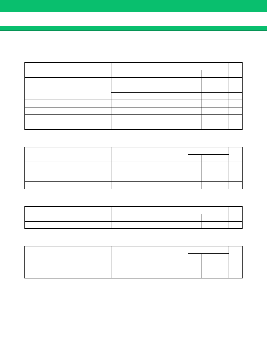
ELECTRICAL CHARACTERISTICS
1.
Reference Section and Error Amp. Section
(Ta = +25
∞
C, V
CC
= 3 V)
2.
Saw-tooth Waveform Oscillator Section
(Ta = +25
∞
C, V
CC
= 3 V)
3.
Under Lockout Protection
(Ta = +25
∞
C, V
CC
= 3 V)
4.
Dead-time Control Section
(Ta = +25
∞
C, V
CC
= 3 V)
Parameter
Symbol
Condition
Value
Unit
Min.
Typ.
Max.
Input threshold voltage
V
T
V
FB
= 450 mV
487
507
527
mV
V
T
input stability
V
TdV1
V
CC
= 2.0 V to 6.0 V
≠5
--
5
mV
V
TdV2
V
CC
= 6.0 V to 15 V
≠5
--
5
mV
V
T
temp. stability
V
TdT
Ta = ≠30∞C to +75∞C
≠3
--
3
%
Input bias current
I
B
V
IN
= 0 V to 0.6 V
≠1.0
≠0.2
1.0
µ
A
Voltage gain
A
V
--
70
100
145
V/V
Frequency band width
BW
A
V
= 0 dB
--
6
--
MHz
Parameter
Symbol
Condition
Value
Unit
Min.
Typ.
Max.
Oscillator frequency
f
OSC
R
T
= 3.0 k
C
T
= 1000 pF
160
200
240
kHz
Frequency input stability
f
dV
V
CC
= 2.0 V to 15 V
--
±
2
--
%
Frequency temp. stability
f
dT
Ta = ≠30∞C to +75∞C
--
±
10
--
%
Parameter
Symbol
Condition
Value
Unit
Min.
Typ.
Max.
Threshold voltage
V
TH
--
--
1.4
--
V
Parameter
Symbol
Condition
Value
Unit
Min.
Typ.
Max.
Max. duty cycle
t
DUTY
C
T
= 1000 pF
R
T
= 3.0k
V
FB
= 0.9 V
60
70
85
%