1
DS04-27402-2E
FUJITSU SEMICONDUCTOR
DATA SHEET
ASSP
POWER-VOLTAGE MONITORING
IC WITH WATCHDOG TIMER
MB3793-
42/30
DESCRIPTION
The MB3793 is an integrated circuit to monitor power voltage; it incorporates a watchdog
timer.
A reset signal is output when the power is cut or falls abruptly. When the power recovers
normally after resetting, a power-on reset signal is output to microprocessor units (MPUs).
An internal watchdog timer with two inputs for system operation diagnosis can provide a
fail-safe function for various application systems.
Two models with detection voltages of 4.2 and 3.0 V are available. There is also a mask
option that can detect voltages of 4.9 to 3.0 V in 0.1-V steps.
The model numbers are MB3793-42 or -30 corresponding to the detected voltage. The
model number and package code are as shown below.
FEATURES
∑
Precise detection of power voltage fall:
±
2.5%
∑
Detection voltage with hysteresis
∑
Low power dispersion: ICC = 27
µ
A (reference)
∑
Internal dual-input watchdog timer
∑
Watchdog-timer halt function (by inhibition pin)
∑
Independently-set watchdog and reset times
∑
Mask option for detection voltage (4.9 to 3.0 V, 0.1-V steps)
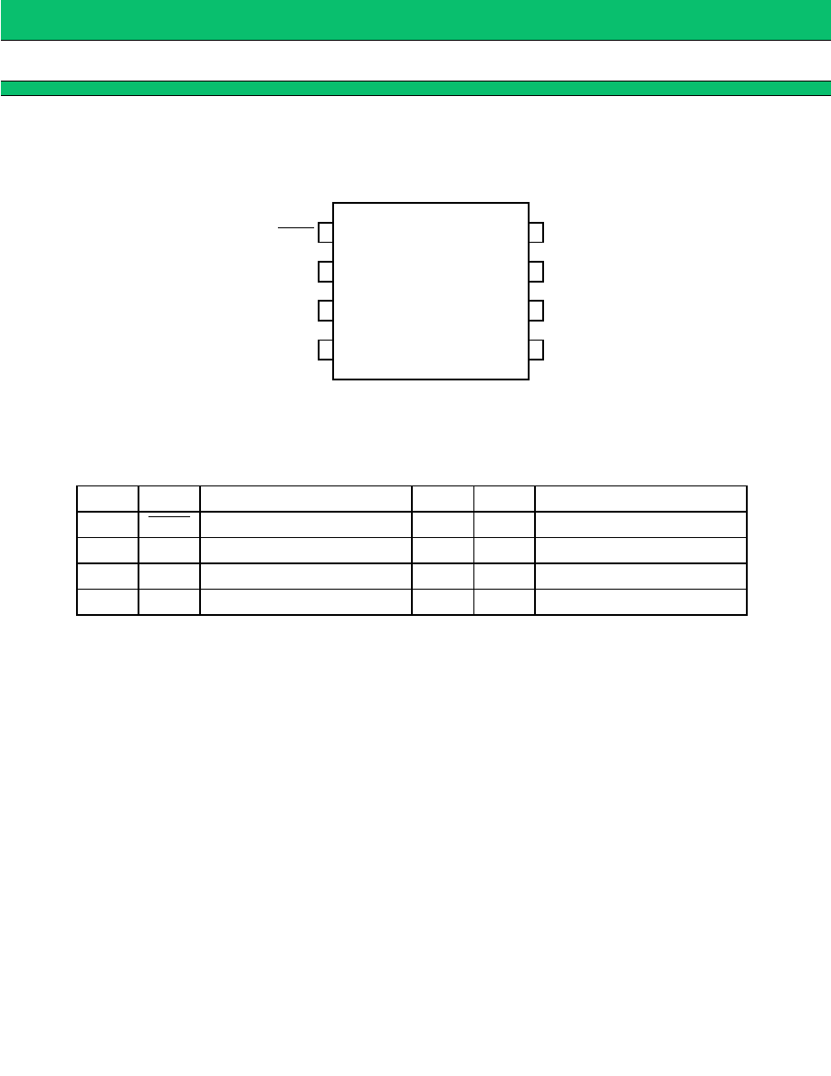
Model No.
Package code
Detection voltage
MB3793-42
3793-A
4.2 V
MB3793-30
3793-N
3.0 V
8-PIN PLASTIC DIP
(DIP-8P-M01)
This device contains circuitry to protect the inputs against
damage due to high static voltages or electric fields. However,
it is advised that normal precautions be taken to avoid
application of any voltage higher than maximum rated voltages
to this high impedance circuit.
8-PIN PLASTIC SOL
(FPT-8P-M02)

4
MB3793
-42/30
s
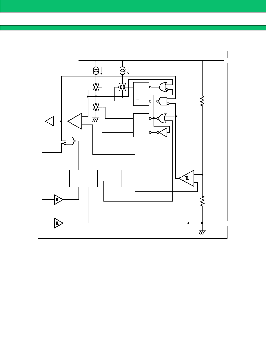
BLOCK FUNCTIONS
1. Comp. S
Comp. S is a comparator with hysteresis to compare the reference voltage with a voltage (V
S
) that is the result of dividing the power voltage
(V
CC
) by resistors 1 and 2. When V
S
falls below 1.24 V, a reset signal is output. This function enables the MB3793 to detect an abnormality
within 1
µ
s when the power is cut or falls abruptly.
2. Comp. O
Comp. O is a comparator to control the reset signal (RESET) output and compares the threshold voltage with the voltage at the CTP pin for
setting the power-on reset hold time. When the voltage at the CTP pin exceeds the threshold voltage, resetting is canceled.
3. Reset output buffer
Since the reset (RESET) output buffer has CMOS organization, no pull-up resistor is needed.
4. Pulse generator
The pulse generator generates pulses when the voltage at the CK1 and CK2 clock pins changes to High from Low level (positive-edge trigger)
and exceeds the threshold voltage; it sends the clock signal to the watchdog timer.
5. Watchdog timer
The watchdog timer can monitor two clock pulses. Short-circuit the CK1 and CK2 clock pins to monitor a single clock pulse.
6. Inhibition pin
The inhibition (INH) pin forces the watchdog timer on/off. When this pin is High level, the watchdog timer is stopped.
7. Flip-flop circuit
The flip-flop circuit RSFF1 controls charging and discharging of the power-on reset hold time setting capacity (C
TP
). The flip-flop circuit RSFF2
switches the charging accelerator for charging C
TP
during resetting on/off. This circuit only functions during resetting and does not function at
power-on reset.