 | –≠–ª–µ–∫—Ç—Ä–æ–Ω–Ω—ã–π –∫–æ–º–ø–æ–Ω–µ–Ω—Ç: MB3853 | –°–∫–∞—á–∞—Ç—å:  PDF PDF  ZIP ZIP |

DS04-29113-4E
FUJITSU SEMICONDUCTOR
DATA SHEET
ASSP
BIPOLAR
1A Motor Drive IC for Motor Applications
MB3853
s
s
s
s
DESCRIPTION
The FUJITSU MB3853 is a motor drive IC with two power driver channels capable of sink/source operation, for
use in two-channel independent operation or H-type drive operation.
The control system and output system have independent power supplies, allowing the control system to be set
to low-voltage operation to conserve power.
Protective circuits are provided for temperature, overvoltage, and overload current, with an open collector type
monitoring terminal.
The MB3853 is designed for use with motors in AV products, office automation products, or cameras, and is also
an ideal IC for use in automated vending equipment and other unmanned operating devices.
s
s
s
s
FEATURES
∑ Circuit configuration
Two sets of built-in control circuits and power circuits
Built-in fly-back diode
∑ Functions
Can drive two motors independently or in H-type drive configurations
Built-in inhibitor function
(Continued)
s
s
s
s
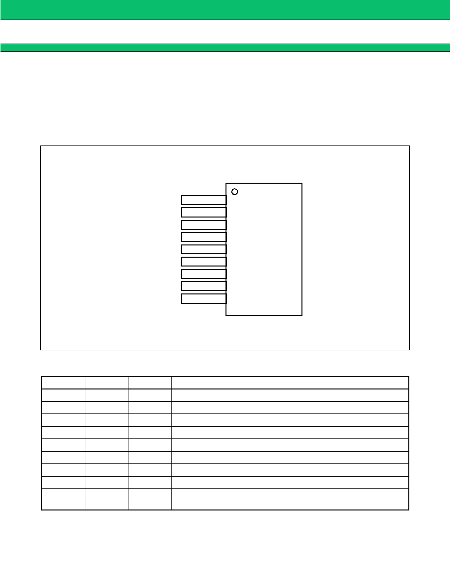
PACKAGE
Plastic SIP, 9 pins
(SIP-9P-M02)
MB3853
2
(Continued)
∑ Input/output terminals
Power supply terminals : Independent control system supply terminal and output system supply terminal
Control terminals : TTL level/CMOS level compatible
Monitor terminal : Open collector type
∑ Space-saving package (SIP9)
s
s
s
s
PIN ASSIGNMENT
s
s
s
s
PIN DESCRIPTION
Pin no.
Symbol
I/O
Description
1
V
CC
1
Control system power supply terminal
2
IN1
I
Load control signal input terminal 1
3
IN2
I
Load control signal input terminal 2
4
OUT2
O
Load control output terminal 2
5
GND
Ground terminal
6
OUT1
O
Load control output terminal 1
7
INH
I
Inhibitor signal input terminal
8
V
CC
2
Output system power supply terminal
9
MONITOR
O
Protective circuit motor signal output terminal (open collector type termi-
nal)
(FRONT VIEW)
(SIP-9P-M02)
1
V
CC
1
IN1
IN2
OUT2
2
3
4
5
6
7
8
9
GND
INH
V
CC
2
MONITOR
OUT1

MB3853
3
s
s
s
s
BLOCK DIAGRAM
INH
IN1
IN2
OUT1
OUT2
GND
V
CC
1
V
CC
2
1
8
7
2
3
5
9
4
6
Power supply circuit
(ON/OFF)
Temperature
protection circuit
Overvoltage
protection circuit
Overload current
protection circuit
Timer circuit
MONITOR
(open collector terminal)
MB3853
4
s
s
s
s
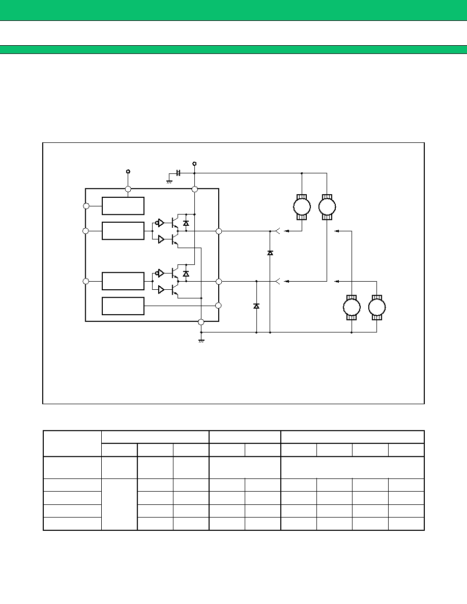
FUNCTIONAL DESCRIPTION
The MB3853 provides two methods for controlling motors. The IC can be connected to two motors and drive
each motor independently, or connected to one motor in an H-type connection and drive the motor in forward
and reverse directions.
1.
Sample connection to 2 motors for run-stop control.
(1) Connection diagram
(2) Table of Functions
: May be either "H" or "L" level
Mode
Input voltage level
Output terminals
Motor operating mode
INH
IN1
IN2
OUT1
OUT2
M2
M3
M2'
M3'
Inhibit mode
"L"
OFF
(high impedance)
Continuous operation
Mode (1)
"H"
"L"
"L"
"H"
"H"
Brake
Brake
Run
Run
Mode (2)
"L"
"H"
"H"
"L"
Brake
Run
Run
Brake
Mode (3)
"H"
"L"
"L"
"H"
Run
Brake
Brake
Run
Mode (4)
"H"
"H"
"L"
"L"
Run
Run
Brake
Brake
M2
M3
M2
M3
OUT1
SW1
SW2
OUT2
SW3
SW4
MONITOR
GND
+
-
100
µ
F
V
CC
2
V
CC
1
INH
IN1
IN2
*
2
*
2
*
1
5
4
6
8
1
7
2
3
9
Power supply
circuit
Run-stop
control
Run-stop
control
Control circuit
Control circuit
Protective
circuits
*1 : The capacitor should be placed close to the IC terminal.
*2 : When using the M2' and M3' terminals, ensure that the OUT1 terminal (pin 6) voltage and
OUT2 terminal (pin 4) voltage do not fall below
-
0.3 V by connecting the OUT1 and OUT2
terminals to ground through a Shottky barrier diode.
◊
◊
◊
MB3853
5
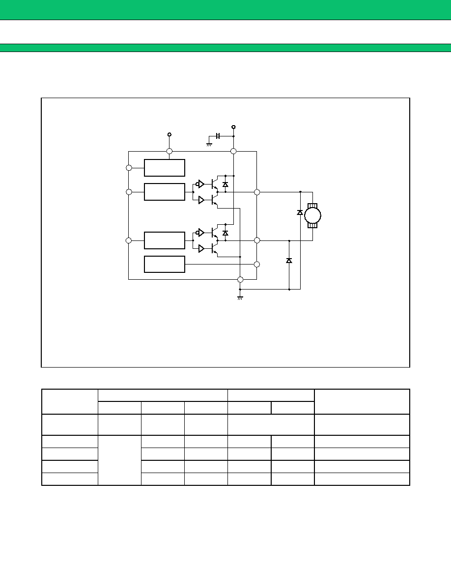
2.
Sample connection to 1 motor for forward-reverse control
(1) Connection diagram
(2) Table of functions
: May be either "H" or "L" level
Mode
Input voltage level
Output terminals
Motor mode
INH
IN1
IN2
OUT1
OUT2
Inhibit mode
"L"
OFF
(High impedance)
Continuous operation
Mode (1)
"H"
"L"
"L"
"H"
"H"
Brake
Mode (2)
"L"
"H"
"H"
"L"
Forward (reverse)
Mode (3)
"H"
"L"
"L"
"H"
Reverse (forward)
Mode (4)
"H"
"H"
"L"
"L"
Brake
M1
OUT1
SW1
SW2
OUT2
SW3
SW4
MONITOR
GND
+
-
100
µ
F *
1
V
CC
2
V
CC
1
INH
IN1
IN2
1
8
6
4
9
5
3
2
7
*
2
*
2
Power supply
circuit
Protective
circuits
Control circuit
Control circuit
Forward-reverse
control
*1 : The capacitor should be placed close to the IC terminal.
*2 : Ensure that the OUT1 terminal (pin 6) voltage and OUT2 terminal (pin 4) voltage do
not fall below
-
0.3 V by connecting the OUT1 and OUT2 terminals to ground through
a Shot key barrier diode.
◊
◊
◊