DS04-71102-1E
FUJITSU SEMICONDUCTOR
DATA SHEET
ASSP for Power Supply Applications
Evaluation Board
MB39A102
s
DESCRIPTION
The MB39A102 evaluation board is a surface mount circuit board with four channels of up conversion, down
conversion and up/down conversion circuits. The internal structure consists of one channel of step-down type,
two channels of transformer type, and one channel of Sepic type. A total of seven lines of output terminals are
provided, supporting voltage settings from -7 V to +15 V and supplying a current Max 500 mA (Sepic type) at a
power-supply voltage between +2.5 V and +6 V. The output circuit (ch1) can be changed to the Zata type by
optional replacement of components. The board incorporates the protective functions that upon detection of a
short circuit or activation of the under voltage lockout protection circuit, the short-circuit protection feature shuts
off transistors to stop the output. Also, the short-circuit detection comparator can detect a short circuit through
an external input (initial number P12). In addition, each channel can be controlled to be turned on and off and
can be set for a soft-start.
s
EVALUATION BOARD SPECIFICATIONS
(Continued)
Terminal
Min
Typ
Max
Unit
Input voltage
VIN
2.5
3.6
6
V
Oscillation frequency
400
500
600
kHz
Output voltage
Vo-1
2.2
2.5
2.8
V
Vo-2-1
13
15
17
Vo-2-2
4.5
5
5.5
Vo-2-3
-
8.3
-
7.5
-
6.7
Vo-3-1
13
15
17
Vo-3-2
4.5
5
5.5
Vo-4
2.9
3.3
3.7
MB39A102
2
(Continued)
s
TERMINAL DESCRIPTION
s
SWITCH DESCRIPTION
Terminal
Min
Typ
Max
Unit
Output current
Vo-1
250
mA
Vo-2-1
10
Vo-2-2
50
Vo-2-3
-
5
Vo-3-1
10
Vo-3-2
50
Vo-4
500
Short-circuit detection
time
4.6
7
12.5
ms
Soft-start time
7.6
10.3
15.8
ms
Symbol
Function
VIN
Power-supply terminal
V
IN
=
2.5 V to 6.0 V (Typ: 3.6 V)
VoX
DC/DC converter output terminal
CTL
Power-supply control terminal
V
CTL
=
0 V to 0.8 V : Standby mode
V
CTL
=
2.0 V to V
IN
: Operation mode
GNDX
DC/DC converter GND terminal
ICGND
MB39A102 GND terminal
SW
NAME
FUNCTION
ON
OFF
1
CS1
CH1 control
Output ON
Output OFF
2
CS2
CH2 control
Output ON
Output OFF
3
CS3
CH3 control
Output ON
Output OFF
4
CS4
CH4 control
Output ON
Output OFF
5
CTL
Power supply control
Operation mode
Standby mode

MB39A102
3
s
SETUP AND CHECKUP
(1) Setup
� Connect the power-supply terminal side to VIN and GND. Connect the Vo side to the required loading device
or measuring instrument.
� Connect a startup power supply from 2.0 V to VIN to the CTL terminal. (This can be done by connection from
VIN.)
� Set SW5 (CTL) to OFF (Standby mode) and SW1 through SW4 (CS1 through CS4) to OFF (output off).
(2) Checkup
� Turn on VIN (power supply), set SW5 to ON (Operation mode) and SW1 through SW4 to ON (output on).
The IC works normally with the following outputs:
Vo1
=
2.5 V (Typ) , Vo2-1
=
15 V (Typ) , Vo2-2
=
5 V (Typ) , Vo2-3
=
-
7.5 V (Typ) , Vo3-1
=
15 V (Typ) ,
Vo3-2
=
5 V (Typ) , Vo4
=
3.3 V (Typ)
MB39A102
4
s
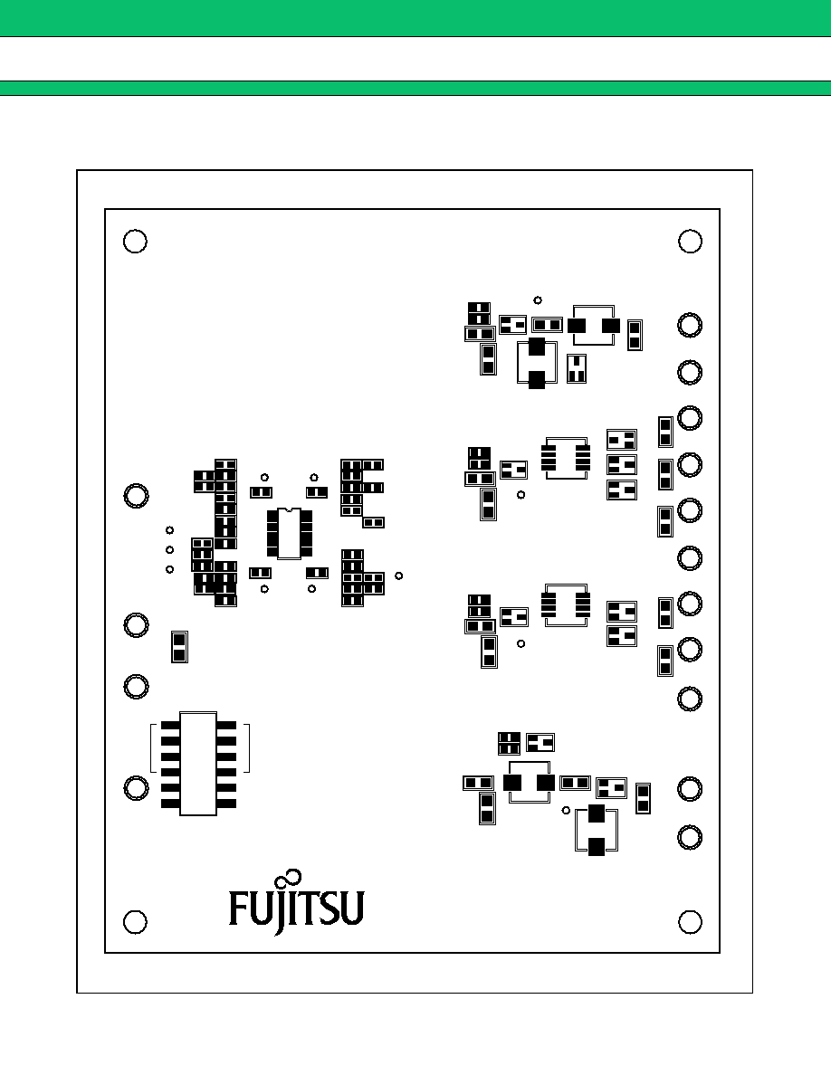
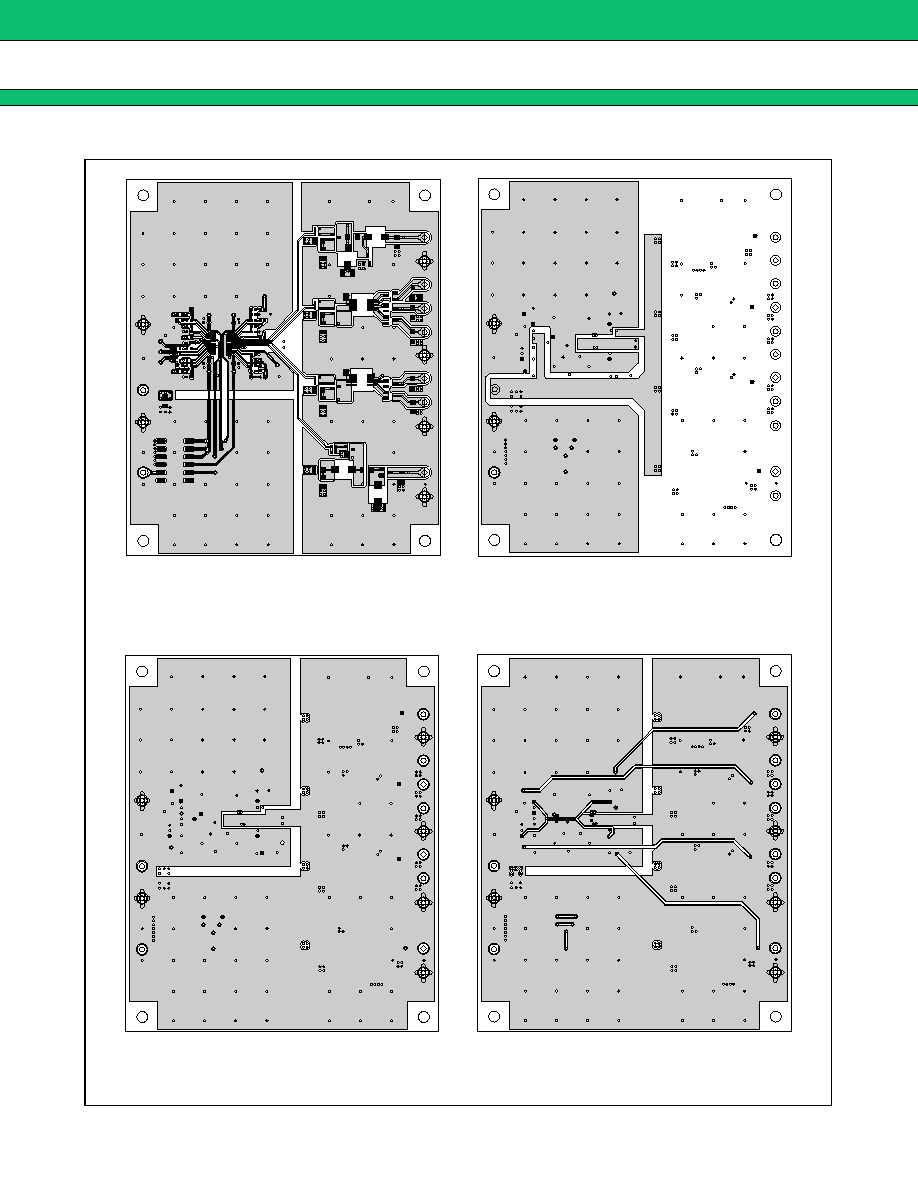
COMPONENT LAYOUT
� On-board Component Layout
(Continued)
Note : Only C1 and C2 parts are set on the rear surface.
MB39A102 EV BOARD
REV. 2. 0
ICGND
VIN
P11
1
15
30
16
R31
P10
P9
GND
CTL
ON
OFF
ON
OFF
1
2
3
4
5
6
C31
R19
R20
R24
R2
C30
C24 C26
C22 C20
R37
R26
R27 P7
P8
P12
P6
M1
P5
R22
R23
R16
R17
R30
R28
R21
R15
R18
R1
R14
C21
R13
R34
R32
R35
C27
R33
R36
C23
C29
C28
R29
C25
R25
C3
Q1
P1
C4
C5
C6
D1
L1
L2
R3
R4
C7
Q2
P2
C8
1
C9
C10
C11
D2
D3
D4
T1
R5
R6
R10
Q4
P3
C13
1
C14
C15
D5
D6
T2
R9
C12
C16
Q5
P4
C17
L4
C18
L3
C19
D7
R11
R12
GND4
V
O
4
GND1
V
O
1
GND3
V
O
3-1
V
O
3-2
GND2
V
O
2-1
V
O
2-2
V
O
2-3
SW1
MB39A102
5
(Continued)
Top side
Inside GND (Layer3)
Inside VIN & GND (Layer2)
Bottom Side