DS07-12536-5E
FUJITSU SEMICONDUCTOR
DATA SHEET
8-bit Proprietary Microcontroller
CMOS
F
2
MC-8L MB89940 Series
MB89943/945/P945/PV940
s
DESCRIPTION
The MB89940 series is specially designed for automotive instrumentation applications. It features a combination
of two PWM pulse generators and four high-drive-current outputs for controlling a stepping motor. It also contains
two analog inputs, two PWM pulse generators and 10-digit LCD controller/driver for various sensor/indicator
devices. The MB89940 series is manufactured with high performance CMOS technologies and packaged in a
48-pin QFP.
s
FEATURES
∑ 8-bit core CPU: 4 MHz system clock (8 MHz external, 500 ns instruction cycle)
∑ 21-bit timebase timer
∑ Watchdog timer
∑ Clock generator/controller
∑ 16-bit interval timer
∑ Two PWM pulse generators with four high-drive-current outputs
∑ Two-channel 8-bit A/D converter
∑ Three external interrupt
∑ Low supply voltage reset
∑ External voltage monitor interrupt
∑ Two more PWM pulse generators for controlling indicator devices
∑ 4-common 17-segment LCD driver/controller
∑ Package: 48-pin plastic QFP, 48-pin ceramic MQFP
∑ 5.0 V single power supply (V
PP
required for MB89P945)
∑ On-chip voltage regulator for internal 3.0 V power supply (MB89943, MB89945)
s
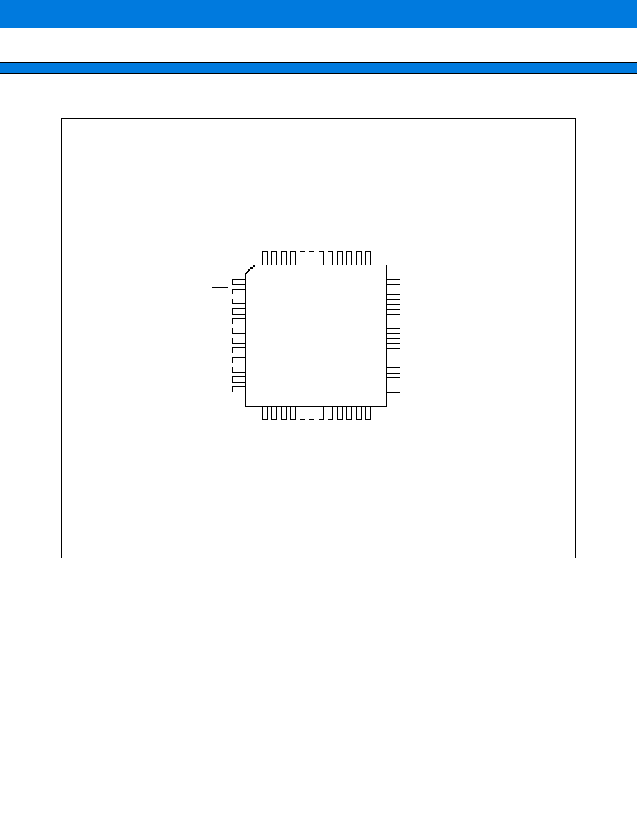
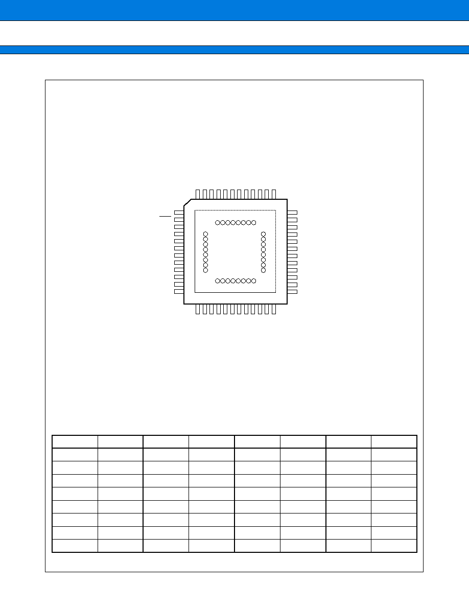
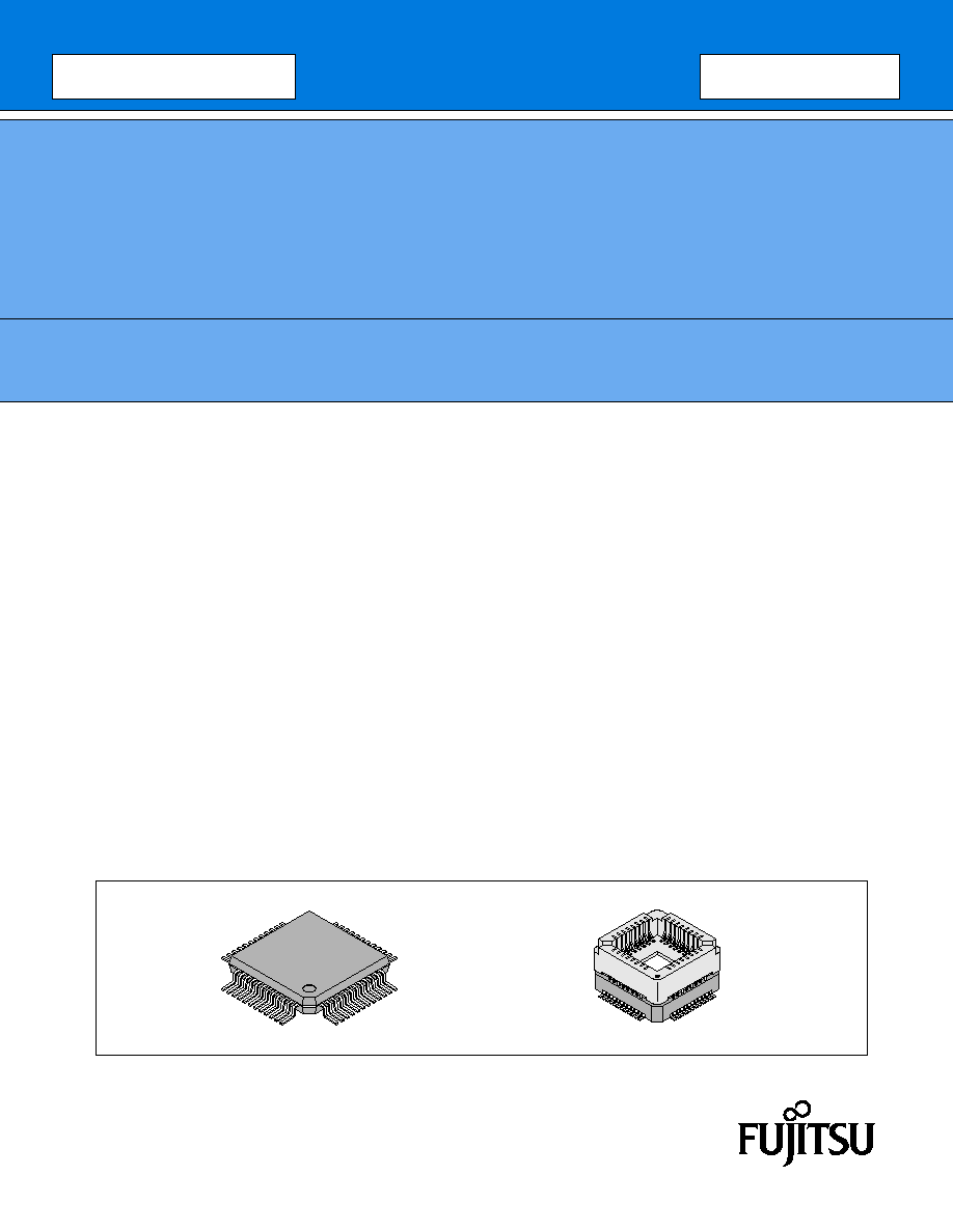
PACKAGES
48-pin Plastic QFP
(FPT-48P-M16)
48-pin Ceramic MQFP
(MQP-48C-P01)
MB89940 Series
2
s
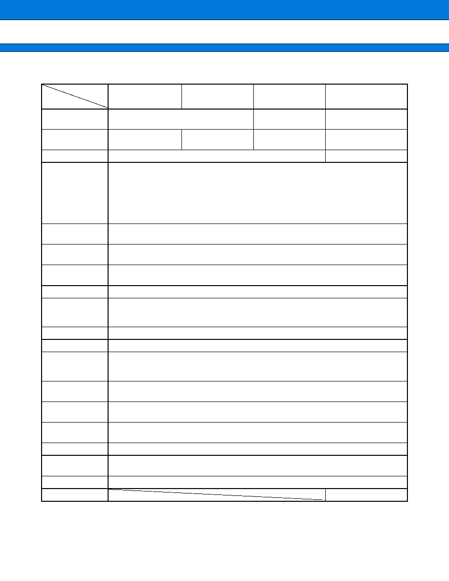
PRODUCT LINEUP
*1: Execution times and clock cycle times are dependent on the use of MCU.
*2: Varies with conditions such as the operating frequency. (See section "
s
Electrical Characteristics.") In the case
of the MB89PV940, the voltage varies with the restrictions of the EPROM for use.
Part number
MB89943
MB89945
MB89P945
MB89PV940
Item
Classification
Mass-produced products
(mask ROM products)
One-time PROM
Piggyback
ROM size
8 K
◊
8 bits
(internal mask ROM)
16 K
◊
8 bits
(internal mask ROM)
16 K
◊
8 bits
(internal ROM)
32 K
◊
8 bits
(external on piggyback)
RAM size
512
◊
8 bits
1 K
◊
8 bits
CPU functions
The number of instructions: 136
Instruction cycle:
0.5
µ
s*
1
@8 MHz
Interrupt response time:
4.0
µ
s*
1
@8 MHz
Multiply instruction time:
19 instruction cycles
Divide instruction time:
21 instruction cycles
Direct addressing memory-to/from-register data transfer:
7 instruction cycles
Ports
Output:
5-bit N-ch open-drain
Input/Output:
Two 8-bit CMOS schmitt I/Os and 8-bit CMOS I/Os
Timebase timer
21 bits
Interrupt interval: 1 ms, 4.1 ms, 32.8 ms or 524.3 ms
8-bit/16-bit timer
Can be used as two 8-bit timers or one 16-bit timer
Operation clock: 1
µ
s, 16
µ
s, 256
µ
s or external *
1
Watchdog Reset
Reset interval: Approx. 524 ms to 1049 ms
Stepping motor
controller
Two 8-bit PWM pulse generators
Synchronized 4-channel high current output
Operation clock: 250 ns, 500 ns, 1
µ
s or 4
µ
s*
1
8-bit PWM timers
Two 8-bit PWM timers
External interrupt
3 channels, selective positive edge or negative edge trigger
A/D converter
8-bit resolution, two-channel input
A/D conversion time : (MB89943/945 : 26
µ
s*
1
/8 MHz oscillation,
MB89P945/MB89PV940 : 22
µ
s*
1
/8MHz oscillation)
LCD controller
4-common and 17-segment outputs
Number of outputs programmable
Low supply voltage
reset
Autonomous reset when low supply voltage
Reset voltage: 3.3 V, 3.6 V, 4.0 V
External voltage
monitor interrupt
Interrupts when voltage at external pin is lower than the reference voltage
Standby modes
Stop mode and sleep mode
Operating
voltage*
2
3.5 V to 5.5 V
Process
CMOS
External EPROM
MBM27C256A-20TVM
MB89940 Series
3
s
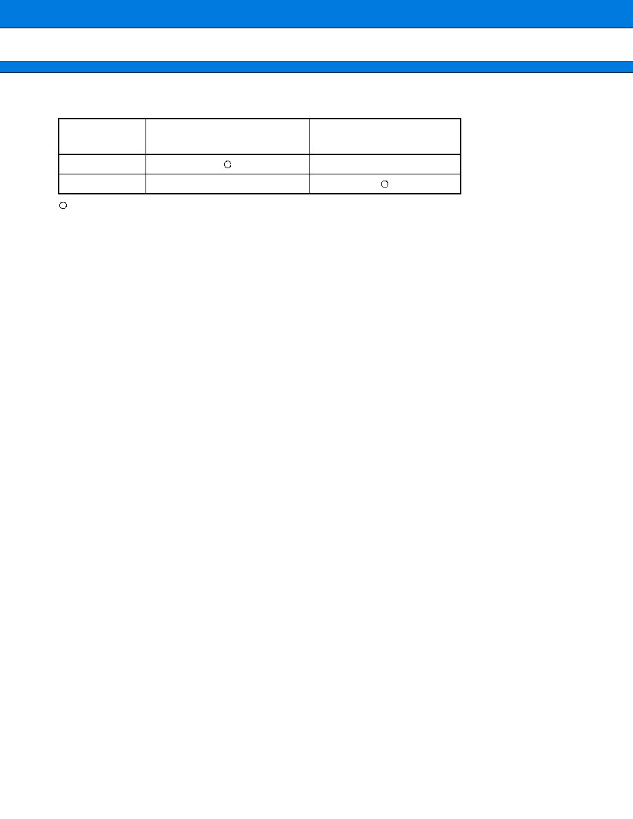
PACKAGE AND CORRESPONDING PRODUCTS
: Available
◊
: Not available
Note: For more information about each package, see section "
s
Package Dimensions."
s
DIFFERENCES AMONG PRODUCTS
1.
Memory Size
Prior to evaluating/developing the software for the MB89940 series, please check the differences between the
product types.
∑ RAM/ROM configurations are dependent on the product type.
∑ If the bottom address of the stack is set to the upper limit of the RAM address, it should be relocated when
changing the product type.
2.
Power Dissipation
∑ For the piggyback product, add the power dissipation of the EEPROM on the piggyback.
∑ The power dissipation differs between the product types.
3.
Technology
The mask ROM product is fabricated with a 0.5
µ
m CMOS technology whereas the other products with 0.8
µ
m
CMOS technology.
Also the mask ROM product contains the on-chip voltage regulator for the internal 3.0 power supply. For details,
refer to
MB89940 Series Hardware Manual
.
4.
Mask Option
Functions that can be selected as options and how to designate these options vary by the product.
Before using options check section "
s
Mask Options."
∑ No options are available for the piggyback product.
∑ The power-on reset and reset output options are always activated with the mask ROM product.
∑ Pull-up option must not be specified with the pins used as LCD outputs.
Package
MB89943
MB89945
MB89P945
MB89PV940
FPT-48P-M16
◊
MQP-48C-P01
◊