
DS07-12545-1E
FUJITSU SEMICONDUCTOR
DATA SHEET
8-bit Proprietary Microcontroller
CMOS
F
2
MC-8L MB89960 Series
MB89965/P965A/F969A/
MB89PV960
s
s
s
s
DESCRIPTION
The MB89960 series is a single-chip microcontroller that utilizes the F
2
MC-8L core for low voltage and high speed
performance. The microcontroller contains a range of peripheral functions including timers, a serial interface, I
2
C
interface, A/D converter, and external interrupts. The internal I
2
C interface complies with the SM bus standard
and supports an SM bus battery controller.
s
s
s
s
FEATURES
∑ Range of package options
∑ QFP and MQFP packages (0.8 mm pitch)
∑ LQFP package (0.5 mm and 0.65 mm pitch)
∑ High speed operation at low voltage
Minimum instruction execution time
=
=
=
=
0.4
µ
s (for a 10 MHz oscillation)
∑ F
2
MC-8L CPU core
Instruction set optimized for controller applications
∑ Multiplication and division instructions
∑ 16-bit arithmetic operations
∑ Bit test branch instructions
∑ Bit manipulation instructions, etc.
∑ Dual-clock control system
∑ Main clock : 10 MHz max.
(Four speed settings available, oscillation halts in sub-clock mode)
∑ Sub-clock : 32.768 kHz (Operation clock for sub-clock mode)
∑ Four channels
∑ 8/16-bit timer/counter (8-bit
◊
2 channels or 16-bit
◊
1 channel)
∑ 21-bit timebase timer
∑ Clock prescaler (15-bit)
∑ Serial I/O
Selectable transfer format (MSB-first or LSB-first) supports communications with a wide range of devices.
∑ A/D converter
10-bit
◊
4 channels
MB89960 Series
2
∑ External interrupts
∑ External interrupt 1 (3 channels)
Three independent interrupt inputs can be used to recover from low-power consumption modes (with edge-
detection function)
∑ External interrupt 2 (1 channel with 8 inputs)
Eight inputs can be used to recover from low-power consumption modes (with "L" level detection function)
∑ Low-power consumption modes (standby modes)
∑ Stop mode (As all oscillations halt in sub-clock mode, current consumption falls to almost zero.)
∑ Sleep mode (The CPU stops to reduce the current consumption to approximately 1/3 of normal.)
∑ Clock mode (All operation halts other than the clock prescaler resulting in very low power consumption.)
∑ I
2
C interface*
∑ Supports Intel SM bus and Philips I
2
C bus standards.
∑ Uses a two-wire data transfer protocol.
∑ Max. 35 I/O ports
∑ Output-only ports (N-ch open drain)
: 6
∑ General-purpose I/O ports (CMOS) : 21
∑ Output-only ports (CMOS)
: 8
* : I
2
C license
The customer is licensed to use the Philips I
2
C patent when using this product in an I
2
C system that complies
with the Philips I
2
C standard specifications.
s
s
s
s
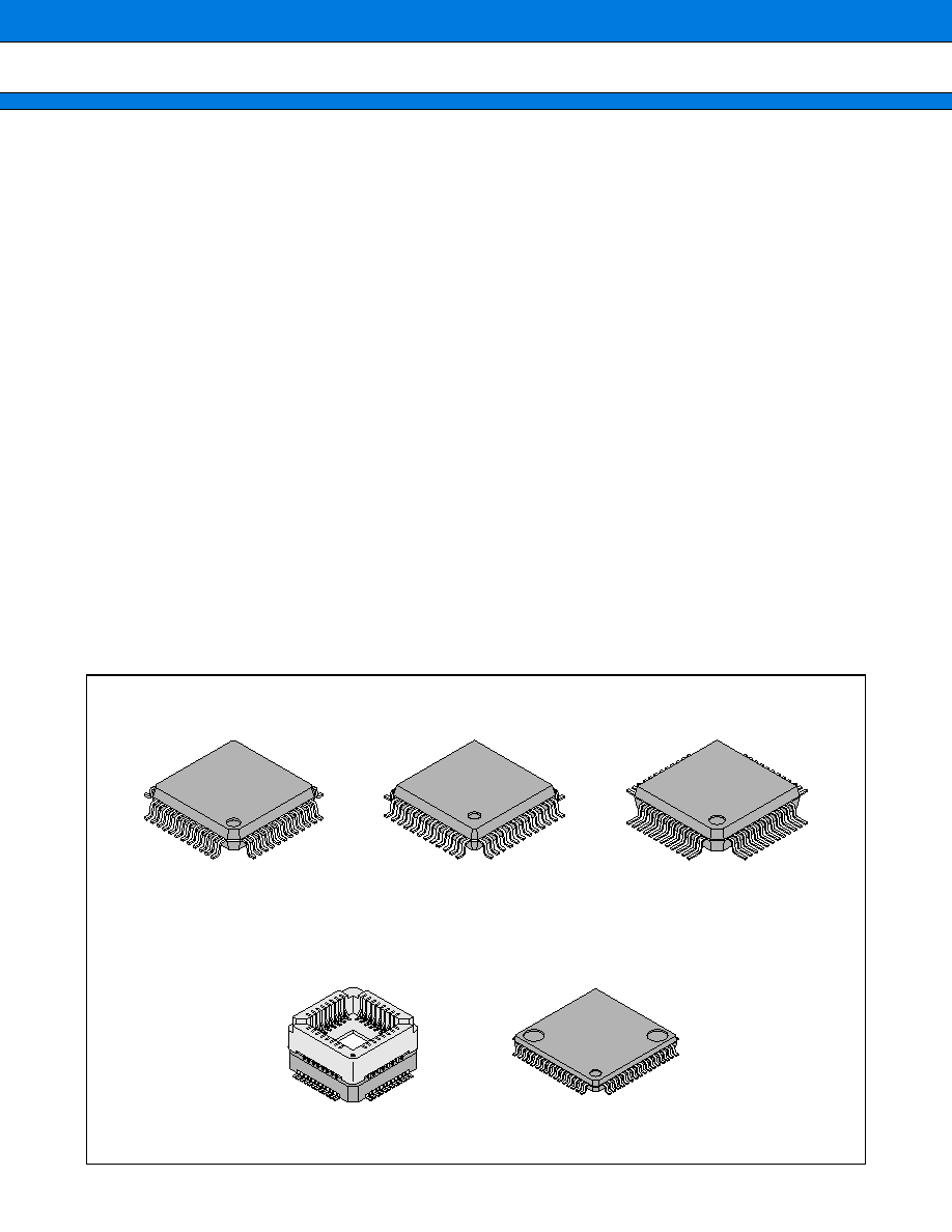
PACKAGE
Plastic LQFP, 48-pin
Plastic QFP, 48-pin
Plastic QFP, 48-pin
(FPT-48P-M05)
(FPT-48P-M13)
(FPT-48P-M16)
Ceramic MQFP, 48-pin
Plastic LQFP, 64-pin
(MQP-48C-P01)
(FPT-64P-M09)
MB89960 Series
3
s
s
s
s
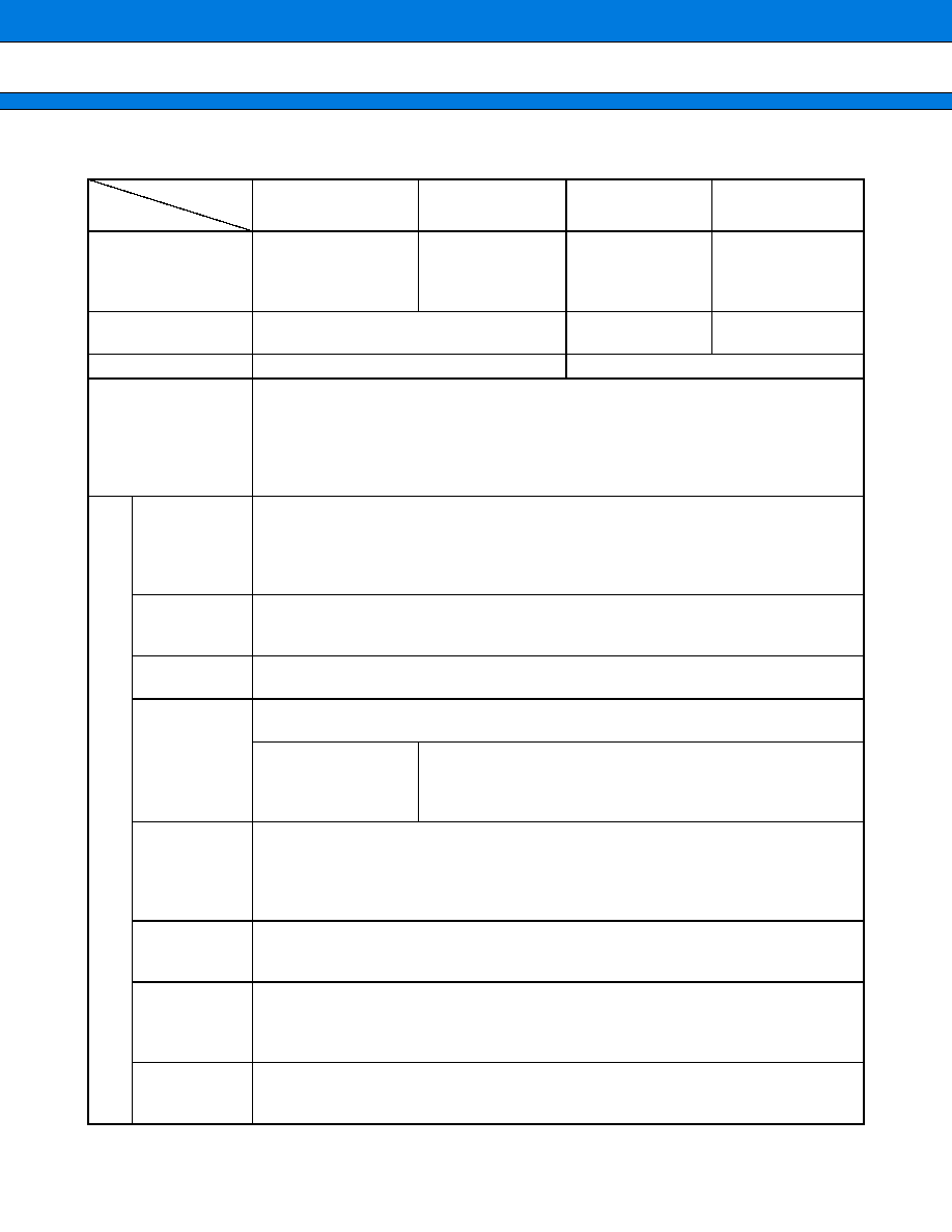
PRODUCT LINEUP
(Continued)
Part No.
Prameter
MB89965
MB89P965A
MB89F969A
MB89PV960
Classification
Mass-produced
products
(mask ROM products)
One-time product
Flash product
Piggyback/
evaluation product
for testing and
development
ROM size
16 K
◊
8-bit (Internal mask ROM)
60 K
◊
8-bit
32 K
◊
8-bit
(External ROM) *
RAM size
512
◊
8-bit
1024
◊
8-bit
CPU functions
Number of instructions
Instruction bit length
Instruction length
Data bit length
Minimum execution time
Interrupt processing time
: 136
: 8-bit
: 1 to 3 bytes
: 1-, 8-, 16bits
: 0.4
µ
s (at 10 MHz)
: 3.6
µ
s (at 10 MHz)
Pe-
riph-
eral
func-
tions
Ports
Output-only ports (N-ch open drain)
Output-only ports (CMOS)
General-purpose I/O ports (CMOS)
Total
: 6 (4 pins are shared with analog inputs)
(2 pins are shared with resource I/O)
: 8
: 21 (shared with resource I/O)
35 (max.)
Timebase timer
21-bit
Four interrupt intervals selectable 0.82 ms, 3.3 ms, 26.2 ms, or 419.4 ms (approx.) (for
main clock)
Watchdog timer
Reset trigger period : 419.4 ms (10 MHz main clock)
500 ms (32.768 MHz sub-clock)
I
2
C interface
One channel. Supports Intel SM bus (version 1.0) and Philips I
2
C bus standards.
Uses a 2-wire protocol for communications with other devices.
Included/Not included
(Specified when order-
ing. See "Ordering In-
formation" for details.)
Included
8/16-bit timer/
counter Timer
2 channel 8-bit timer/counter operation (independent operation clocks for timer 1 and
timer 2) or 16-bit timer/counter operation (operation clock period : 0.8
µ
s to 204.8
µ
s)
can execute an event counter operation and output a square wave using an external
Clock.
1 or 16-bit timer/counter operation mode
Serial I/O
8 bits
LSB-first or MSB-first selectable
Transfer clocks : External or three internal clocks (0.8
µ
s, 3.2
µ
s, 12.8
µ
s)
External
interrupt 1
(edge)
Selectable edge detection (rising, falling, or either edge)
3 independent channels
These can also be used to recover from standby modes (edge detection is still available
in stop mode) .
External
interrupt 2
(level)
1 channel with 8 inputs ("L" level interrupts, independent input enable)
This can also be used to recover from standby modes (level detection is still available in
stop mode) .
MB89960 Series
4
(Continued)
* : Use the MBM27C256A-20TVM as the external ROM (Operating voltage : 4.5 V to 5.5 V)
Note : Unless otherwise stated, clock periods and conversion times are for 10 MHz operation with the main clock
operating at maximum speed.
s
s
s
s
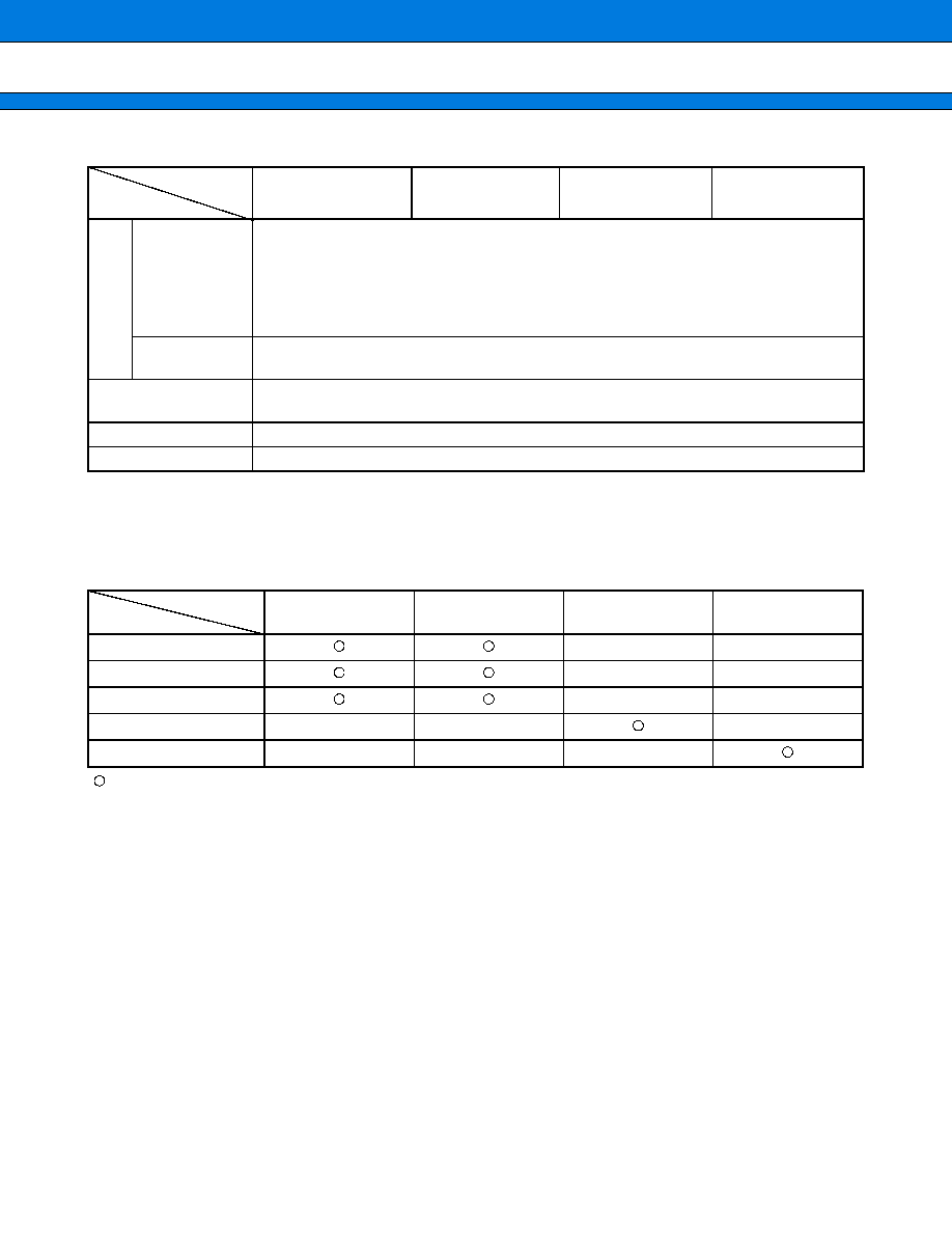
PACKAGES AND CORRESPONDING PRODUCTS
: Available
: Not available
Part No.
Prameter
MB89965
MB89P965A
MB89F969A
MB89PV960
Pe-
riph-
eral
func-
tions
A/D converter
4 channel
◊
10-bit resolution
A/D conversion time : 15.2
µ
s (MB89965, MB89P965A, MB89F969A)
13.2
µ
s (MB89PV960)
Continuous activation is available using the output from the 8/16-bit timer/counter or
timebase timer.
Reference voltage input (AVR)
Clock prescaler
15-bit
Interrupt interval : 31.25 ms, 0.25 s, 0.50 s, 1.00 s (for a 32.768 kHz sub-clock)
Low power consump-
tion (standby modes)
Sleep mode, stop mode, and clock mode
Process
CMOS
Operating voltage
3.5 V to 5.5 V
Package
Part No.
MB89965
MB89P965A
MB89F969A
MB89PV960
FPT-48P-M05
FPT-48P-M13
FPT-48P-M16
FPT-64P-M09
MQP-48C-P01
◊
◊
◊
◊
◊
◊
◊
◊
◊
◊
◊
◊
◊
MB89960 Series
5
s
s
s
s
DIFFERENCES AMONG PRODUCTS
1.
Memory Space
Please take note of the differences among products before testing and developing software for the MB89960
series.
∑ The RAM and ROM configurations differ among products.
∑ If the bottom stack address is set at the top RAM address, this will need to be relocated if changing to a different
product.
2.
Current Consumption
∑ In the case of the MB89PV960, add the current consumed by the EPROM which is connected to the top socket.
∑ When operated at low speed, one-time PROM and EPROM products will consume more current than mask
ROM products. However, the current consumption in sleep/stop modes is the same.
3.
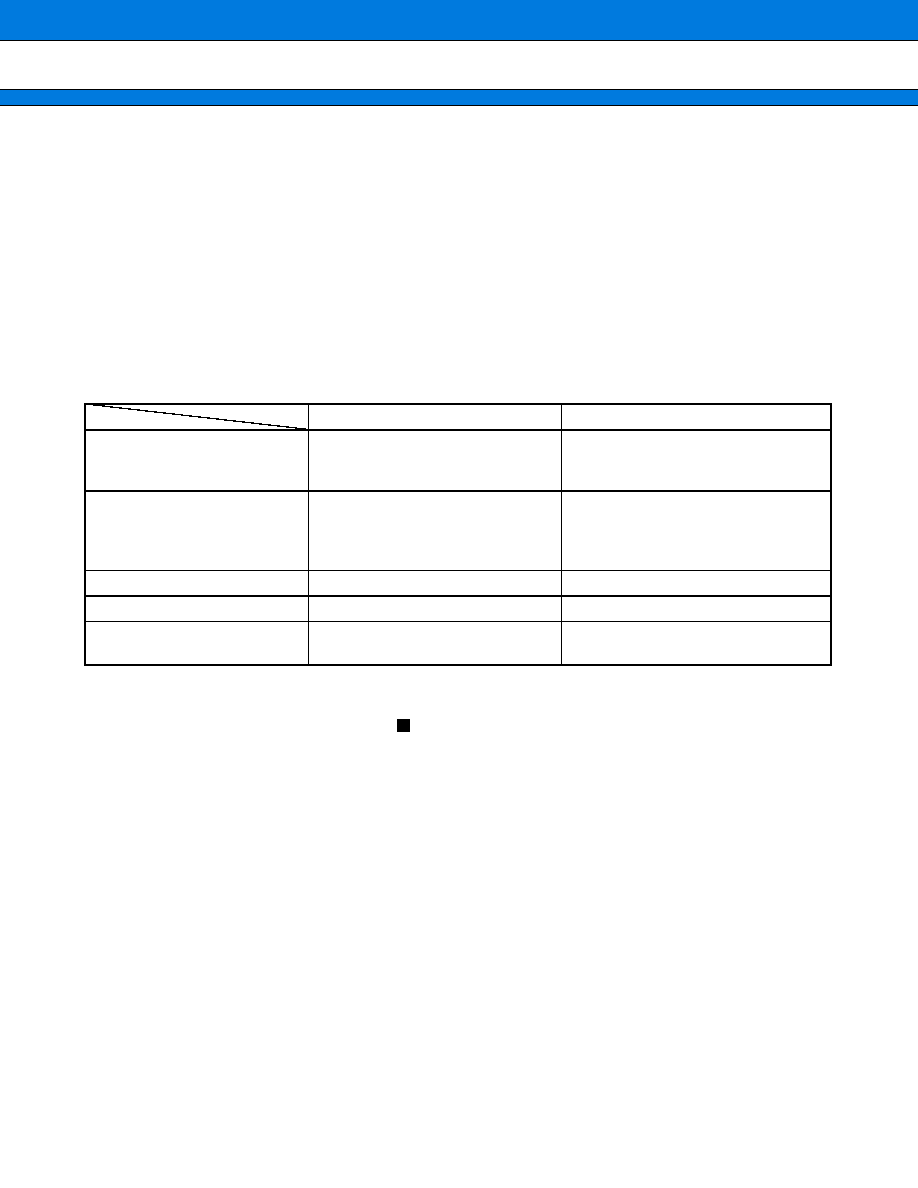
Functional Differences Between MB89960 Series
4.
Mask Options
Functions that can be selected as options and the methods used to specify these options vary by the product.
Before using mask options, check section "
Mask Options".
MB89965/P965A/F969A
MB89PV960
Power-on reset delay time
Regulator stabilization delay time,
regulator recovery time,
oscillation stabilization delay time
Oscillation stabilization delay time
External reset delay time in stop/
sub-clock mode or external
interrupt delay time in main stop
mode
Regulator recovery time,
oscillation stabilization delay time
Oscillation stabilization delay time
Port pin pull-up resistors
Software-selectable
Not available
A/D conversion time
38 instruction cycles
33 instruction cycles
I
2
C noise elimination circuit
Always present regardless of ICCR :
DMPB bit setting
Disabled if ICCR : DMPB bit
=
"1"