DS07-12529-1E
FUJITSU SEMICONDUCTOR
DATA SHEET
8-bit Proprietary Microcontroller
CMOS
F
2
MC-8L MB89950 Series
MB89951/953/P955/PV950
s
OUTLINE
The MB89950 series of single-chip compact microcontroller using the F
2
MC*-8L family core which can operate
at high-speeds and low voltages. They contain peripherals such as timers, UART, serial interfaces, external
interrupts and a 168-pixel LCD controller/driver. It is best suited for use in LCD panels.
*: F
2
MC stands for FUJITSU Flexible Microcontroller.
s
FEATURES
· Minimum instruction execution time: 0.8
µ
s at 5 MHz
· F
2
MC-8L family CPU core
(Continued)
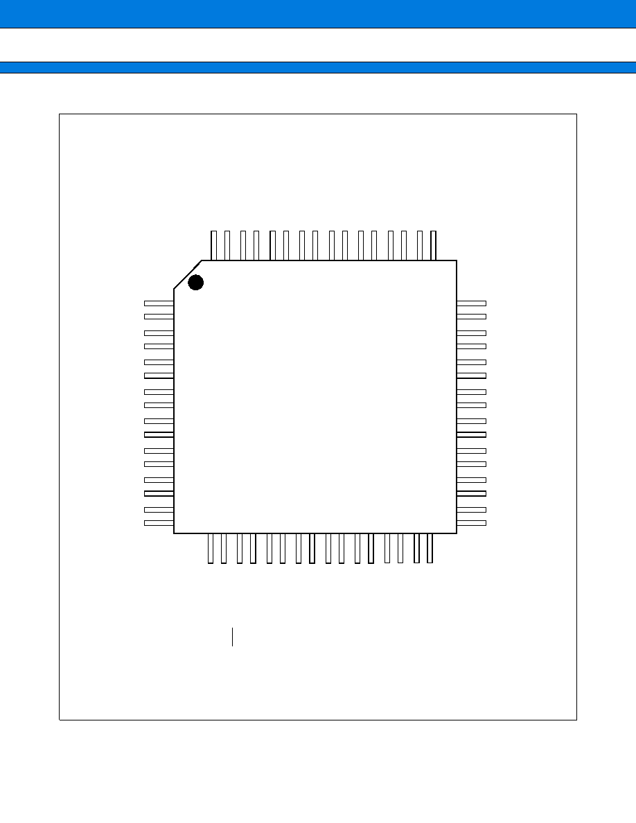
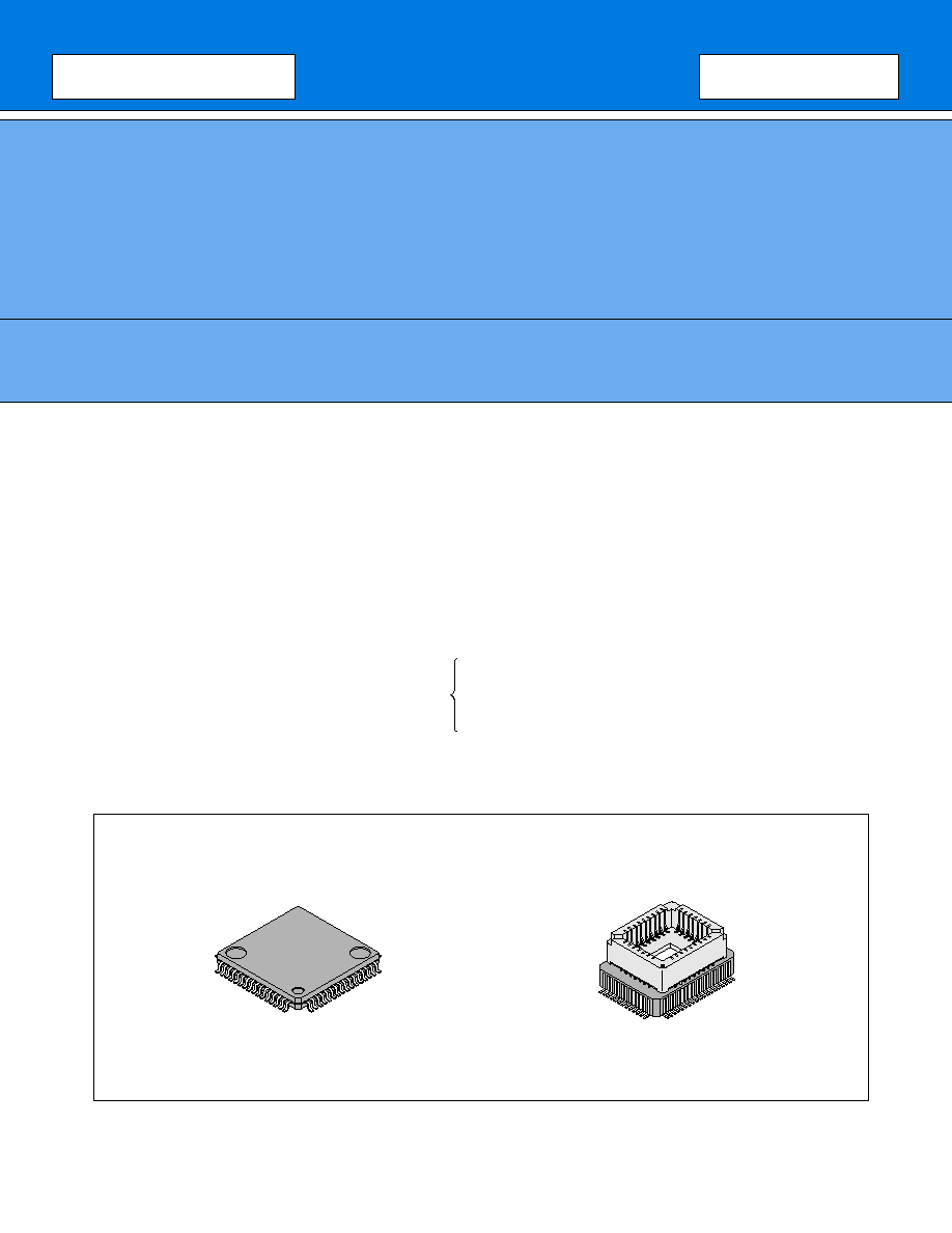
s
PACKAGE
Multiplication and division instructions
16-bit arithmetic operation
Instruction test and branch instruction
Bit manipulation instruction, etc.
Instruction system most suited to controllers
64-pin Plastic QFP
(FPT-64P-M09)
64-pin Ceramic MQFP
(MQP-64C-P01)

MB89950 Series
2
(Continued)
· LCD controller/driver
Maximum 42 segment outputs x 4 common outputs
Build-in LCD driver split resistor
· Three-channel timer unit
8-bit PWM timer: (usable as both reload timer and PWM timer)
8-bit pulse width counter timer: (usable as both reload timer)
20-bit timebased counter
· Two serial interfaces
8-bit synchronous serial interface
UART (5, 7, and 8-bit transfers possible)
· External-interrupt input: 2 channels
2 channels can be used to clear the low-power consumption modes
An edge detection function is provided for each channel
· Low-power consumption modes
Stop mode (Oscillation stops to minimize the current consumption)
Sleep mode (CPU stops to reduce current consumption to about 30%)
· Package: QFP-64 (0.65mm pitch)
MB89950 Series
3
s
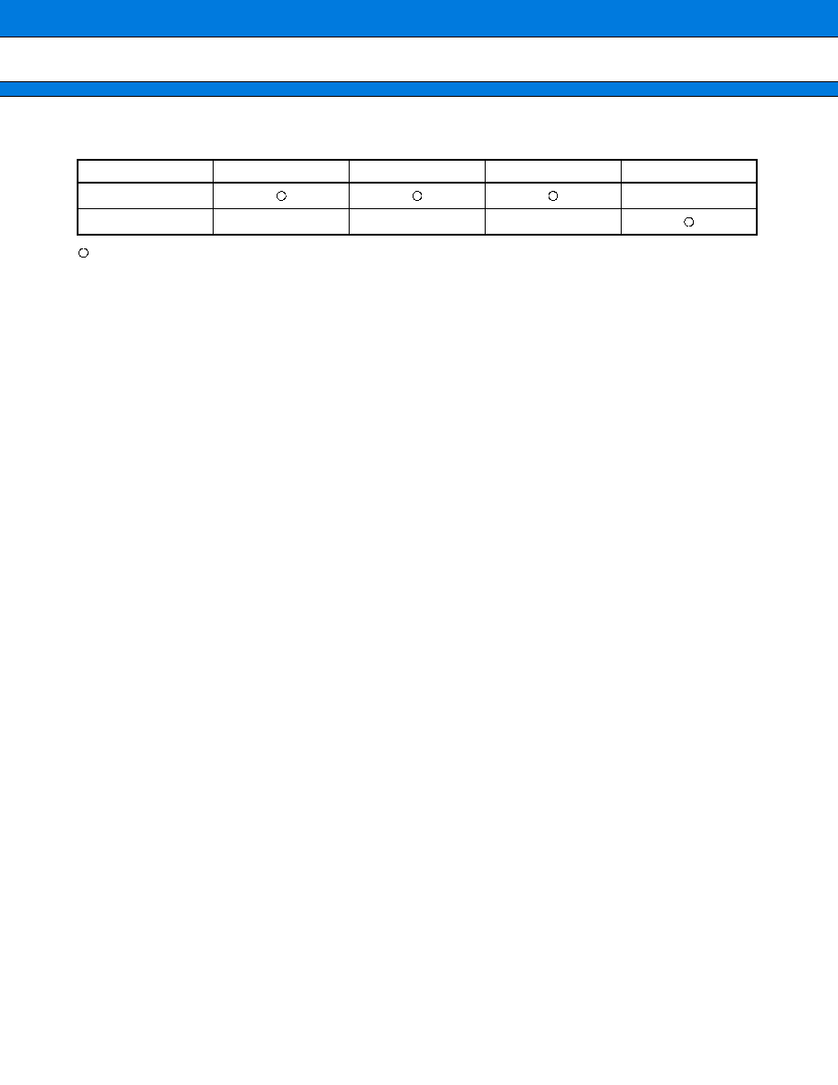
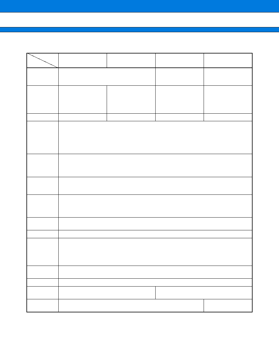
PRODUCT LINEUP
*1: Mask Option.
*2: Varies with conditions such as the operating frequency. (See "
s
Electrical Characteristics".)
MB89953
MB89P955
MB89PV950
Classification
Mass-produced products
(Mask ROM product)
One-time
PROM
products
Piggyback/
evaluation and
development ptoduct
ROM size
4 K
×
8 bits
(internal mask ROM)
8 K
×
8 bits
(internal mask ROM)
16 K
×
8 bits
(internal PROM, to be
programmed with
general-purpose
EPROM programmer)
32 K
×
8 bits
(external ROM)
RAM size
128
×
8 bits
256
×
8 bits
512
×
8 bits
1024
×
8 bits
CPU functions
The number of basic instructions:
136
Instruction bit length:
8 bits
Instruction length:
1 to 3 bytes
Data bit length:
1, 8, 16 bits
Minimum imstruction execution time:
0.8
µ
s at 5 MHz (V
CC
=5.0 V)
Interrupt processing time:
7.2
µ
s at 5 MHz (V
CC
=5.0 V)
Ports
I/O port (N-ch open-drain):
22 (also used as segment pin)*
1
I/O port (N-ch open-drain):
4 (two of them are also used as LCD bias pins)
I/O port (CMOS):
7 (6 used as peripheral)
Total:
33 (max.)
8-bit PWM
timer
8-bit reload timer operation (toggle output possible)
8-bit resolution PWM operation
Operation clock (pulse-width count timer output: 0.8
µ
s, 12.8
µ
s, 51.2
µ
s/5 MHz)
8-bit
pulse-width
counter timer
8-bit reload timer operation
8-bit pulse width measurement (continuous measurement, High- and Low-width measurement,
and one-cycle measurement)
Operation clock (0.8
µ
s, 3.2 ms, 25.6
µ
s/5 MHz)
8-bit serial I/O
8-bit length, selectable from least significant bit (LSB) first or most significant bit (MSB) first,
transfer clock (external, 1.6
µ
s, 6.4 ms, 25.6
µ
s/5 MHz)
UART
5-, 7-, 8-bit transfers possible, internal baud-rate generator (Max. 78125 bps/5 MHz)
LCD controller/
driver
Common output: 4
Segment output: 42 (max.)
Operation mode: 1/2 bias and 1/2 duty, 1/3 bias and 1/3 duty, 1/3 bias and 1/4 duty
LCD controller display RAM capacity: 42
×
4 bits
LCD driver split resistor: built-in (external resistor selectable)
External
interrupt
2 (edge selectable: one serving as pulse-width count timer input)
Standby mode
Sleep mode, stop mode
Power supply
voltage*
2
2.2 V to 6.0 V
2.7 V to 6.0 V
EPROM --
MBM27C256A-20TV
(LCC package)
MB89951
Part number
Item