Äîêóìåíòàöèÿ è îïèñàíèÿ www.docs.chipfind.ru

DS07-13505-5E
FUJITSU SEMICONDUCTOR
DATA SHEET
16-bit Proprietary Microcontroller
CMOS
F
2
MC-16F MB90246A Series
MB90246A
s
DESCRIPTION
The MB90246A series is a 16-bit microcontroller optimum to control mechatronics such as a hard disk drive unit.
The instruction set of F
2
MC-16F CPU core inherits AT architecture of F
2
MC*-16/16H family with additional
instruction sets for high-level languages, extended addressing mode, enhanced multiplication/division
instructions, and enhanced bit manipulation instructions. The microcontroller has a 32-bit accumulator for
processing long word data (32-bit).
The MB90246A series contains a production addition unit as peripheral resources for enabling easy
implementation of functions supported by IIR and FIR digital filters. It also supports a wealth of peripheral functions
including:
- an 8/10-bit A/D converter having eight channels;
- an 8-bit D/A converter having three channels;
- UART;
- an 8-bit PWM timer having four channels;
- a timer having three plus one channels;
- an input capture (ICU) having two channels; and
- a DTP/external interrupt circuit having four channels.
* : F
2
MC stands for FUJITSU Flexible Microcontroller.
s
PACKAGE
100-pin Plastic LQFP
(FPT-100P-M05)

2
MB90246A Series
s
FEATURES
· Clock
Operating clock can be selected from divided-by-2, 4, 8 or 32 of oscillation (at oscillation of 32 MHz, 1 MHz
to 16 MHz).
Minimum instruction execution time of 62.5 ns (at machine clock of 16 MHz)
· CPU addressing space of 16 Mbytes
Internal addressing of 24-bit
External accessing can be performed by selecting 8/16-bit bus width (external bus mode)
· Instruction set optimized for controller applications
Rich data types (bit, byte, word, long word)
Rich addressing mode (23 types)
High code efficiency
Enhanced precision calculation realized by the 32-bit accumulator
Signed multiplication/division instruction
· Instruction set designed for high level language (C) and multi-task operations
Adoption of system stack pointer
Enhanced pointer indirect instructions
Barrel shift instructions
· Enhanced execution speed
8-byte instruction queue
· Enhanced interrupt function
Priority levels: 8 levels
External interrupt input ports: 4 ports
· Automatic data transmission function independent of CPU operation
Extended intelligent I/O service function (EI
2
OS)
· Low-power consumption (stand-by) mode
Sleep mode (mode in which CPU operating clock is stopped)
Stop mode (mode in which oscillation is stopped)
Hardware stand-by mode
Gear function
· Process
CMOS technology
· I/O port
General-purpose I/O ports (CMOS): 38
General-purpose I/O ports (TTL): 11
General-purpose I/O ports (N-ch open-drain): 8
Total: 57
· Timer
Timebase timer/watchdog timer: 1 channel
8-bit PWM timer: 4 channels
16-bit re-load timer: 3 channels
· 16-bit I/O timer
16-bit free-run timer: 1 channel
Input capture (ICU): 2 channels
· I/O simple serial interface
Clock synchronized transmission can be used.
· UART: 1 channel
Clock asynchronized or clock synchronized serial transmission can be selectively used.
· DTP/external interrupt circuit: 4 channels
A module for starting extended intelligent I/O service (EI
2
OS) and generating an external interrupt triggered
by an external input.
(Continued)

3
MB90246A Series
(Continued)
· Delayed interrupt generation module
Generates an interrupt request for switching tasks.
· 8/10-bit A/D converter: 8 channels
8-bit or 10-bit resolution can be selectively used.
Starting by an external trigger input.
· 8-bit D/A converter
Resolution: 8 bits
×
3 channels
· DSP interface for the IIR filter
Function dedicated to IIR calculation
Up to eight items of results of signed multiplication of 16
×
16 bits are added.
Execution time of
: 0.625
µ
s (When oscillation is 32 MHz and when N = M =3)
Up to three N and M values can be set at your disposal.
Yk =
bn Yk n +
am Xk m
N
M
n = 0
m = 0
4
MB90246A Series
s
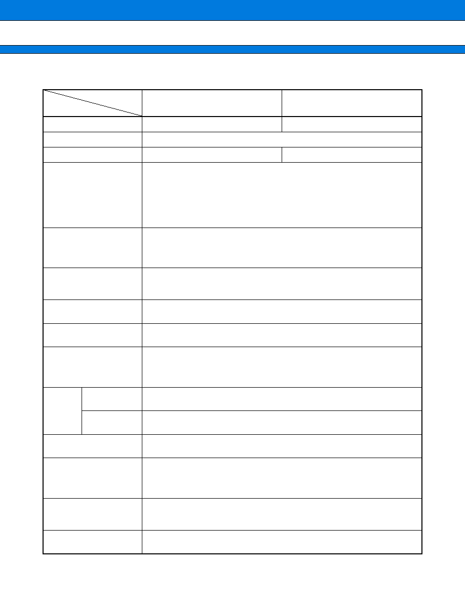
PRODUCT LINEUP
(Continued)
MB90V246
Classification
Mass-produced product
Evaluation product
ROM size
None
RAM size
4 k
×
8 bits
6 k
×
8 bits
CPU functions
The number of instructions: 412
Instruction bit length: 8 bits, 16 bits
Instruction length: 1 byte to 7 bytes
Data bit length: 1 bit, 4 bits, 8 bits, 16 bits, 32 bits
Minimum execution time: 62.5 ns (at machine clock of 16 MHz)
Interrupt processing time: 1.0
µ
s (at machine clock of 16 MHz, minimum
value)
Ports
General-purpose I/O ports (CMOS output): 38
General-purpose I/O ports (TTL input): 11
General-purpose I/O ports (N-ch open-drain output): 8
Total: 57
Timebase timer
18-bit counter
Interrupt interval: 0.256 ms, 1.024 ms, 4.096 ms, 16.384 ms
(at oscillation of 32 MHz)
Watchdog timer
Reset generation interval: 3.58 ms, 14.33 ms, 28.67 ms, 57.34 ms
(at oscillation of 32 MHz, minimum value)
8/16-bit PWM timer
Number of channels: 4
Pulse interval: 0.25
µ
s to 32.77 ms (at oscillation of 32 MHz)
16-bit re-load timer
Number of channels: 3
16-bit re-load timer operation
Interval: 125 ns to 131 ms (at machine clock of 16 MHz)
External event count can be performed.
16-bit
I/O timer
16-bit free-run
timer
Number of channel: 1
Overflow interrupts or intermediate bit interrupts may be generated.
Input capture
(ICU)
Number of channel: 2
Rewriting a register value upon a pin input (rising, falling, or both edges)
I/O simple serial interface
Number of channels: 2
Clock synchronized transmission (62.5 kbps to 8 Mbps)
UART
Clock asynchronized transmission (2404 bps to 500 kbps)
Clock synchronized transmission (250 kbps to 2 Mbps)
Transmission can be performed by bi-directional serial transmission or by
master/slave connection.
DTP/external interrupt circuit
Number of inputs: 4
Started by a rising edge, a falling edge, an "H" level input, or an "L" level input.
External interrupt circuit or extended intelligent I/O service (EI
2
OS) can be used.
Delayed interrupt generation
module
An interrupt generation module for switching tasks
used in real-time operating systems.
MB90246A
Item
Part number

5
MB90246A Series
(Continued)
* : Varies with conditions such as the operating frequency. (See section "
s
Electrical Characteristics.") Assurance
for the MB90V246 is given only for operation with a tool at a power voltage of 4.5 V to 5.5 V, an operating
temperature of 0 to 70 degrees centigrade, and an clock frequency of 1.6 MHz to 32 MHz.
Note: A 64-word RAM for product addition is supported in addition to the above RAMs.
s
PACKAGE AND CORRESPONDING PRODUCTS
: Available
×
: Not available
Note: For more information about each package, see section "
s
Package Dimensions."
s
DIFFERENCES AMONG PRODUCTS
Memory Size
In evaluation with an evaluation chips, note the difference between the evaluation chip and the chip actually used.
The RAM size is 4 Kbytes for the MB90246A, and 6 Kbytes for the MB90V246.
MB90V246
8/10-bit A/D converter
Conversion precision: 10-bit or 8-bit can be selectively used.
Number of inputs: 8
One-shot conversion mode (converts selected channel only once)
Continuous conversion mode (converts selected channel continuously)
Stop conversion mode (converts selected channel and stop operation repeatedly)
8-bit D/A converter
Number of channels: 3
Resolution: 8 bits
Based on the R-2R system
DSP interface for the IIR
filter
Function dedicated to IIR calculation
Up to 8 items of results of signed
multiplication of 16
×
16 bits are added.
Execution time of
: 0.625
µ
s
(When oscillation is 32 MHz and when N = M = 3)
Up to three N and M values can be set at your disposal.
Low-power consumption
(stand-by) mode
Sleep/stop/hardware stand-by/gear function
Process
CMOS
Power supply voltage for
operation*
4.5 V to 5.5 V
Package
MB90246A
MB90V246
FPT-100P-M05
×
PGA-256C-A02
×
MB90246A
Yk =
bn Yk n +
am Xk m
N
M
n = 0
m = 0
Item
Part number
Document Outline