DS07-13715-3E
FUJITSU SEMICONDUCTOR
DATA SHEET
16-bit Proprietary Microcontrollers
CMOS
F
2
MC-16LX MB90560/565 Series
MB90561/561A/562/562A/F562/F562B/V560
MB90567/568/F568
s
DESCRIPTION
The MB90560/565 series is a general-purpose 16-bit microcontroller designed for industrial, OA, and process
control applications that require high-speed real-time processing. The device features a multi-function timer able
to output a programmable waveform.
The microcontroller instruction set is based on the same AT architecture as the F
2
MC-8L and F
2
MC-16L families
with additional instructions for high-level languages, extended addressing modes, enhanced signed multiplication
and division instructions, and a complete range of bit manipulation instructions. The microcontroller has a
32-bit accumulator for processing long word (32-bit) data.
s
FEATURES
∑ Clock
∑ Internal oscillator circuit and PLL clock multiplication circuit
∑ Oscillation clock
Clock speed selectable from either the machine clock, main clock, or PLL clock. The main clock is the oscillation
clock divided into 2 (0.5 MHz to 8 MHz for a 1 MHz to 16 MHz base oscillation) . The PLL clock is the oscillation
clock multiplied by one to four (4 MHz to 16 MHz for a 4 MHz base oscillation) .
∑ Minimum instruction execution time : 62.5 ns (for oscillation
=
4 MHz, PLL clock setting
=
◊
4, V
CC
=
5.0 V)
∑ Maximum CPU memory space : 16 MB
∑ 24-bit addressing
∑ Bank addressing
(Continued)
s
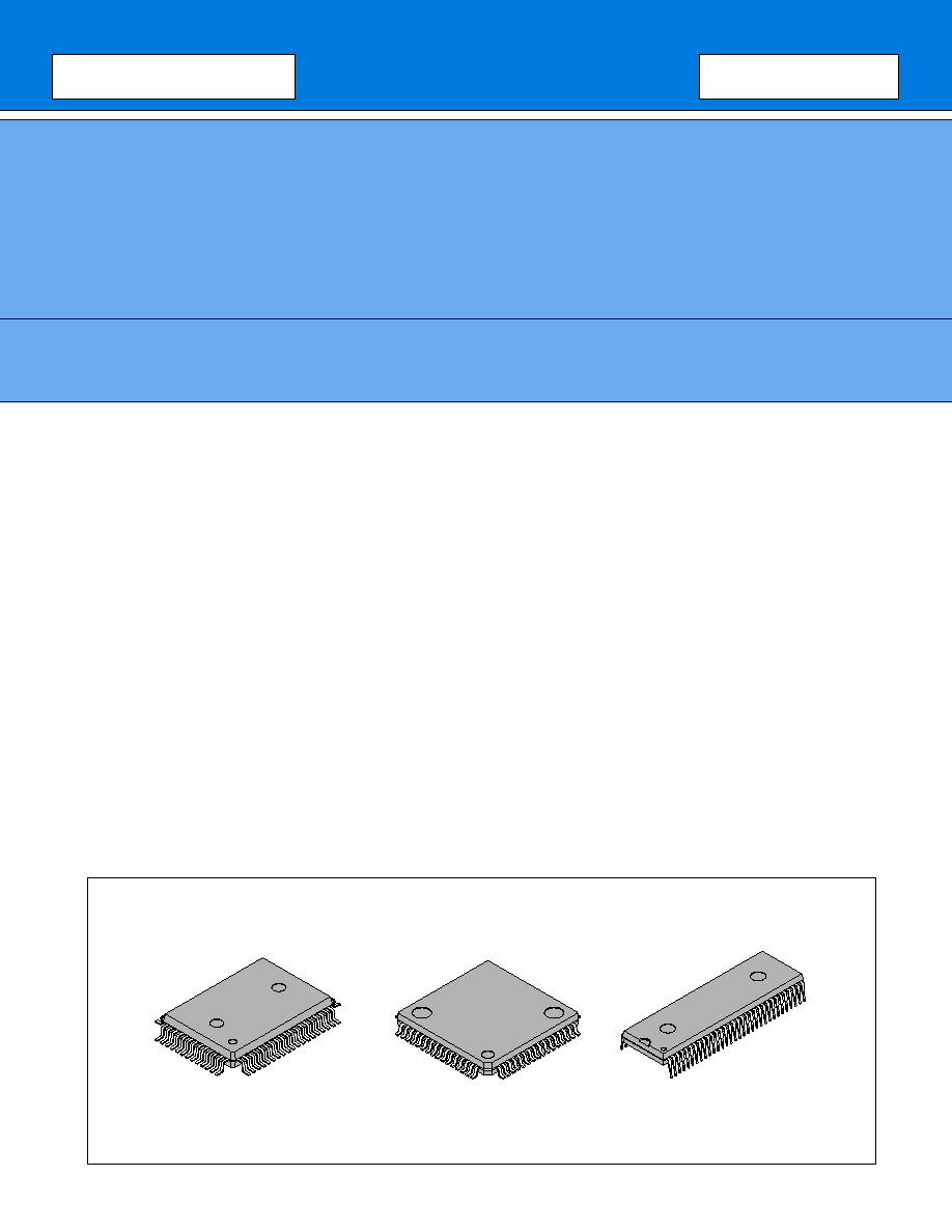
PACKAGES
64-pin plastic QFP
64-pin plastic LQFP
64-pin plastic SH-DIP
(FPT-64P-M06)
(FPT-64P-M09)
(DIP-64P-M01)

MB90560/565 Series
2
(Continued)
∑ Instruction set
∑ Bit, byte, word, and long word data types
∑ 23 different addressing modes
∑ Enhanced calculation precision using a 32-bit accumulator
∑ Enhanced signed multiplication and division instructions and RETI instruction
∑ Instruction set designed for high level language (C) and multi-tasking
∑ Uses a system stack pointer
∑ Symmetric instruction set and barrel shift instructions
∑ Program patch function (2 address pointers) .
∑ 4-byte instruction queue
∑ Interrupt function
∑ Priority levels are programmable
∑ 32 interrupts
∑ Data transfer function
∑ Extended intelligent I/O service function : Up to 16 channels
∑ Low-power consumption modes
∑ Sleep mode (CPU operating clock stops.)
∑ Timebase timer mode (Only oscillation clock and timebase timer continue to operate.)
∑ Stop mode (Oscillation clock stops.)
∑ CPU intermittent operation mode (The CPU operates intermittently at the specified interval.)
∑ Package
∑ LQFP-64P (FTP-64P-M09 : 0.65 mm pin pitch)
∑ QFP-64P (FTP-64P-M06 : 1.00 mm pin pitch)
∑ SH-DIP (DIP-64P-M01 : 1.778 mm pin pitch)
∑ Process : CMOS technology
s
PERIPHERAL FUNCTIONS (RESOURCES)
∑ I/O ports : 51 ports (max.)
∑ Timebase timer : 1 channel
∑ Watchdog timer : 1 channel
∑ 16-bit reload timer : 2 channel 5
∑ Multi-function timer
∑ 16-bit free-run timer : 1 channel
∑ Output compare : 6 channels
Can output an interrupt request when a match occurs between the count in the 16-bit freerun timer and the
value set in the compare register.
∑ Input capture : 4 channels
On detecting an active edge on the input signal from an external input pin, copies the count value of the 16-
bit freerun timer to the input capture data register and generates an interrupt request.
∑ 8/16-bit PPG timer (8-bit
◊
6 channels or 16-bit
◊
3 channels) The period and duty of the output pulse can
be set by the program.
∑ Waveform generator (8-bit timer : 3 channels)
∑ UART : 2 channels
∑ Full-duplex, double-buffered (8-bit)
∑ Can be set to asynchronous or clock synchronous serial transfer (I/O expansion serial) operation
∑ DTP/external interrupt circuit (8 channels)
∑ External interrupts can activate the extended intelligent I/O service.
∑ Generates interrupts in response to external interrupt inputs.

MB90560/565 Series
3
∑ Delayed interrupt generation module
∑ Generates an interrupt request for task switching.
∑ 8/10-bit A/D converter : 8 channels
∑ 8-bit or 10-bit resolution selectable
MB90560/565 Series
4
s
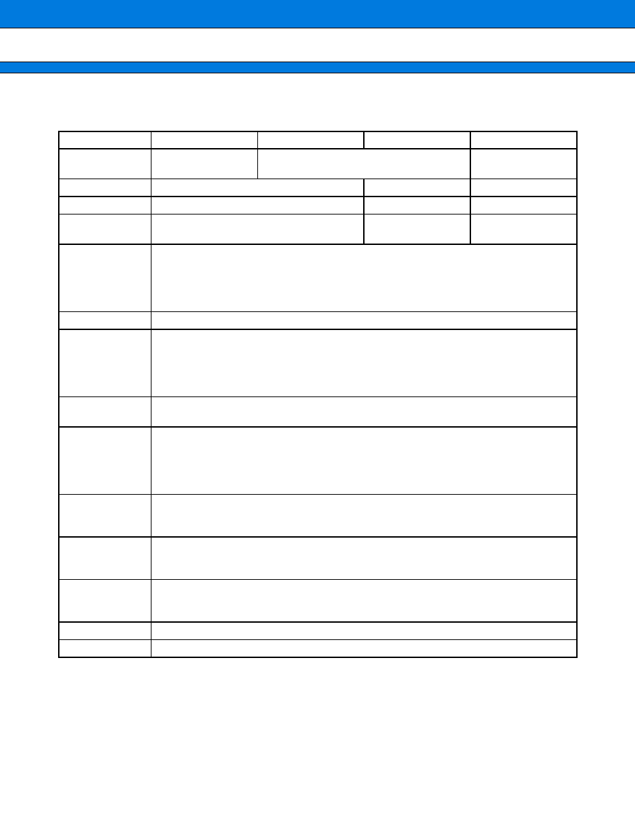
PRODUCT LINEUP
1.
MB90560 Series
* : DIP switch setting (S2) when using the emulation pod (MB2145-507) .
Refer to "2.7 Dedicated Emulator Power Supply" in the "MB2145-507 Hardware Manual" for details.
Part Number
MB90F562/B
MB90562/A
MB90561/A
MB90V560
Classification
Internal flash memory
product
Internal mask ROM product
Evaluation product
ROM size
64 Kbytes
32 Kbytes
No ROM
RAM size
2 Kbytes
1 Kbytes
4 Kbytes
Dedicated emula-
tor power supply
*
No
CPU functions
Number of instructions : 351
Minimum instruction execution time : 62.5 ns for a 4 MHz oscillation (with
◊
4 multiplier)
Addressing modes : 23 modes
Program patch function : 2 address pointers
Maximum memory space : 16 Mbytes
Ports
I/O ports (CMOS) : 51
UART
Full-duplex, double-buffered
Clock synchronous or asynchronous operation selectable
Can be used as I/O serial
Internal dedicated baud rate generator
2 channels
16-bit reload timer
16-bit reload timer operation
2 channels
Multi-function
timer
16-bit free-run timer
◊
1 channel
Output compare
◊
6 channels
Input capture
◊
4 channels
8/16-bit PPG timer (8-bit
◊
6 channels or 16-bit
◊
3 channels)
Waveform generator (8-bit timer
◊
3 channels) 3-phase waveform output, deadtime output
8/10-bit
A/D converter
8 channels (multiplexed input)
8-bit or 10-bit resolution selectable
Conversion time : 6.13
µ
s (min.) (for maximum machine clock speed 16 MHz)
DTP/external
interrupts
8 channels (8 channels available, shared with A/D input)
Interrupt triggers :
"L"
"H" edge, "H"
"L" edge, "L" level, "H" level (selectable)
Low power
consumption
modes
Sleep mode, timebase timer mode, stop mode, and CPU intermittent operation mode
Process
CMOS
Operating voltage
5 V
±
10
%

MB90560/565 Series
5
2.
MB90565 Series
* : DIP switch setting (S2) when using the emulation pod (MB2145-507) .
Refer to "2.7 Dedicated Emulator Power Supply" in the "MB2145-507 Hardware Manual" for details.
Part Number
MB90F568
MB90568
MB90567
Classification
Internal flash memory product
Internal mask ROM product
ROM size
128 Kbytes
96 Kbytes
RAM size
4 Kbytes
4 Kbytes
Dedicated emula-
tor power supply
*
CPU functions
Number of instructions : 351
Minimum instruction execution time : 62.5 ns for a 4 MHz oscillation (with
◊
4 multiplier)
Addressing modes : 23 modes
Program patch function : 2 address pointers
Maximum memory space : 16 Mbytes
Ports
I/O ports (CMOS) : 51
UART
Full-duplex, double-buffered
Clock synchronous or asynchronous operation selectable
Can be used as I/O serial
Internal dedicated baud rate generator
2 channels
16-bit reload timer
16-bit reload timer operation
2 channels
Multi-function
timer
16-bit free-run timer
◊
1 channel
Output compare
◊
6 channels
Input capture
◊
4 channels
8/16-bit PPG timer (8-bit
◊
6 channels or 16-bit
◊
3 channels)
Waveform generator (8-bit timer
◊
3 channels) 3-phase waveform output, deadtime output
8/10-bit A/D
converter
8 channels (multiplexed input)
8-bit or 10-bit resolution selectable
Conversion time : 6.13
µ
s (min.) (for maximum machine clock speed 16 MHz)
DTP/external
interrupts
8 channels (8 channels available, shared with A/D input)
Interrupt triggers :
"L"
"H" edge, "H"
"L" edge, "L" level, "H" level (selectable)
Low power con-
sumption modes
Sleep mode, timebase timer mode, stop mode, and CPU intermittent operation mode
Process
CMOS
Operating voltage 3.3 V
±
0.3 V