DS07-13718-1E
FUJITSU SEMICONDUCTOR
DATA SHEET
16-Bit Original Microcontroller
CMOS
F
2
MC-16LX MB90M405 Series
Built in FL Display Controller Circuit
MB90MF408/M408/M407/MF408A/
MB90M408A/M407A
s
DESCRIPTION
The MB90M405 series is a general-purpose 16-bit microcontroller, developed for applications requiring fluorescent
display tube panel control. Each microcontroller is equipped with 60 highly voltage-resistant output pins, needed
for fluorescent display control. The command structure inherits the same AT architecture as the F
2
MC-8L and
F
2
MC-16L, in order to provide enhanced C-language support, improved extended/signed multiplication/division
instructions in addressing mode, and enhanced bit processing. In addition, an onboard 32-bit accumulator allows
long word processing.
Note : F
2
MC stands for FUJITSU Flexible MicroController, and is a registered trademark of Fujitsu Limited.
s
FEATURES
� Clock
� Internal PLL clock multiplication circuit
� Oscillation clock
1/2 main oscillation clock
1-4x PLL oscillation clock (2.1 MHz to 16.8 MHz at 4.2 MHz oscillation) , can be set from machine clock
� Minimum instruction execution time : 59.5 ns (operating at 4.2 MHz oscillation, 4x PLL clock, V
CC
=
3 V)
� Oscillation clock can generate 1/16, 1/32, 1/64, and 1/128 external clock outputs.
� Maximum memory space : 16 Mbytes
� Can also use 24-bit addressing
(Continued)
s
PACKAGE
100-pin plastic QFP
(FPT-100P-M06)

MB90M405 Series
2
� Command structure optimized for controller applications
� Able to handle following data types : bit, byte, word, and long word
� 23 types of addressing mode
� High code efficiency (compiler)
� Enhanced calculation precision using a 32-bit accumulator
� Enhanced signed multiplication and division instructions and RETI instructions
� Command structure supports C language/multitasking
� Employs system stack pointers
� Instruction set had symmetry and barrel shift instruction functions
� Program patch functions (2-address pointers)
� Improved execution speed
� 4-byte built-in instruction queue allows instructions to be read ahead of time, speeding up execution.
� Interrupt function
� 8 programmable priority level settings
� Incorporates powerful 32-factor interrupt function
� Data transfer function
� Extended intelligent I/O service function : allows up to 16 channels to be set
� Low-power consumption modes
� Sleep mode (CPU operation clock stops)
� Timebase timer mode (oscillation clock and timebase timer operate)
� Stop mode (oscillation clock stops)
� CPU intermittent operation mode (CPU operates intermittently at the specified intervals)
� Package
� QFP-100 (FPT-100P-M06 : 0.65 mm pin pitch)
� Process
� CMOS technology
� I/O ports : Maximum 26 (26 ports, also used for internal resources)
� Timebase timer : 1 channel
� Watchdog timer : 1 channel
� 16-bit reload timer : 3 channels
� 16-bit freerun timers : 1 channel
� Output compare : 1 channel
� If the count value of the 16-bit freerun timer and compare register setting match, an interrupt request can
be output
� Input capture : 2 channels
� By detecting a valid edge in a signal input from the external input pin, it is possible to read the 16-bit freerun
timer count into the input capture data register, and output an interrupt request.
� Serial I/O : 2 channels
� UART : 2 channels
� Includes full-duplex double buffer (8 bits length)
� Can be set to asynchronous transfer or clock-synchronized serial transfer (I/O extended serial)
� DTP/external interrupt (4 channels)
� Extended intelligent I/O service can be started via external input
� It is possible to generate an internal hardware interrupt via external input
� Delayed interrupt generation module
� It is possible to output task switching interrupt requests
� 8/10 bit A/D converter (16 channels)
� Choice of 8 and 10-bit resolution selectable
(Continued)

MB90M405 Series
3
(Continued)
� FL-control circuit
� FL driver control enabled (up to 32 digits and up to 59 segments with automatic display control)
- Any number between 1 and 32 digits can be set
- Dimmer setting possible
� LED driver control enabled (up to 16 with automatic display control)
- Up to 16 automatic display control possible at 1/2 duty
� Time clock output circuit
� Can be set to 1/32, 1/64, 1/128, or 1/256 of oscillation clock
MB90M405 Series
4
s
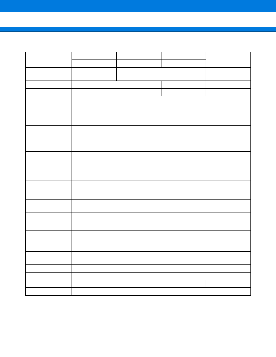
PRODUCT LINEUP
*1 : All FL-output pins (FIP0 to FIP59) have pull downs
*2 : Some FL-output pins (FIP0 to FIP16) do not have pull downs. The remaining FL-output pins (FIP17 to FIP59)
have pull downs.
Part Number
MB90MF408
*1
MB90M408
*1
MB90M407
*1
MB90MV405
MB90MF408A
*2
MB90M408A
*2
MB90M407A
*2
Classification
Internal flash
memory type
Internal mask ROM type
Evaluation
ROM size
128 Kbytes
96 Kbytes
None onboard
RAM size
4 Kbytes
4 Kbytes
4 Kbytes
CPU functions
Number of basic instructions
Minimum instruction execution time
Addressing modes
Program patch function
Maximum memory space
: 351
: 59.5 ns/4.2 MHz (with x4 multiplier)
: 23
: 2 address pointers
: 16 Mbytes
Ports
26 (CMOS) I/O ports (26 ports, also used for resources)
FL-control circuit
60 FL outputs possible (during LED control, 43 FL output and 17 LED control)
FL and LED driver control enabled
During FL driver control, both digit and segment dimmer setting possible
Serial I/O (UART)
Includes full-duplex double buffer
Clock-synchronized/asynchronous settings available
Can also be used as clock synchronized extended I/O serial
Also equipped with dedicated baud rate generator
4 channels built in (2 channels also used for UART)
16-bit reload timers
16-bit reload timer operation (can be set to toggle or one-shot output)
Event count function can be set
3 channels built in
16-bit freerun timer
One 16-bit output comparison channel (for clearing freerun timer)
Two 16-bit input capture channels
8/10 bit
A/D converter
16 channels (input multiplex)
Choice of 8 and 10-bit resolution available
Conversion time : 5.9
�
s (when machine clock operating at 16.8 MHz)
Time clock
output circuit
Possible to divide external input clock and output externally
Programmable divisions : 16/32/64/128
I
2
C Bus
One I
2
C interface channel built in
DTP/external
interrupt
4 independent channels (also used with A/D input)
Interrupt factors : can be set to "L"
"H" edge/"H"
"L" edge/"L" level/"H" level
Low-power modes
Sleep mode/timebase timer mode, stop mode, and intermittent CPU mode
Process
CMOS
Package
QFP-100 (0.65 mm pitch)
PGA256
Operating voltage
3.3 V
�
0.3 V (16.8 MHz : 4.2 MHz 4x)

MB90M405 Series
5
s
PIN ASSIGNMENTS
(TOP VIEW)
(FPT-100P-M06)
1
2
3
4
5
6
7
8
9
10
11
12
13
14
15
16
17
18
19
20
21
22
23
24
25
26
27
28
29
30
FIP16/LED16
FIP17
FIP18
FIP19
FIP20
FIP21
FIP22
FIP23
FIP24
FIP25
V
SS
-IO
FIP26
FIP27
FIP28
FIP29
FIP30
FIP31
FIP32
FIP33
FIP34
FIP35
FIP36
V
DD
-FIP
FIP37
FIP38
FIP39
FIP40
FIP41
FIP42
FIP43
80
79
78
77
76
75
74
73
72
71
70
69
68
67
66
65
64
63
62
61
60
59
58
57
56
55
54
53
52
51
PB7/AN15/INT3
PB6/AN14/INT2
PB5/AN13/SO2/TO0
RST
PB4/AN12/SC2/TIN0
PB3/AN11/SI2
PB2/AN10
PB1/AN9
PB0/AN8
PA7/AN7
PA6/AN6
PA5/AN5
PA4/AN4
PA3/AN3
PA2/AN2
PA1/AN1
PA0/AN0/TMCK
AV
SS
A
VCC
P91/SCL/SC3
P90/SDA/SO3
P87/SO1
P86/SC1
P85/SI1
P84/SO0
P83/SC0
P82/SI0
P81/IC1/INT1
P80/IC0/INT0
MD2
100
99
98
97
96
95
94
93
92
91
90
89
88
87
86
85
84
83
82
81
FIP15/LED15
FIP14/LED14
FIP13/LED13
FIP12/LED12
FIP11/LED11
FIP10/LED10
FIP9/LED9
FIP8/LED8
FIP7/LED7
FIP6/LED6
FIP5/LED5
FIP4/LED4
FIP3/LED3
FIP2/LED2
FIP1/LED1
FIP0/LED0
V
CC
-CPU
X1
X0
V
SS
-CPU
31
32
33
34
35
36
37
38
39
40
41
42
43
44
45
46
47
48
49
50
FIP44
FIP45
FIP46
FIP47
FIP48
FIP49
FIP50
FIP51
FIP52
FIP53
FIP54
V
SS
-IO
FIP55
FIP56
FIP57
FIP58
FIP59
V
KK
MD0
MD1