 | –≠–ª–µ–∫—Ç—Ä–æ–Ω–Ω—ã–π –∫–æ–º–ø–æ–Ω–µ–Ω—Ç: GPH3V3-50 | –°–∫–∞—á–∞—Ç—å:  PDF PDF  ZIP ZIP |
Hercules Series, Page 1
Part No. 98≠002 Rev. 1.1
WWW.GALAXYPWR.COM
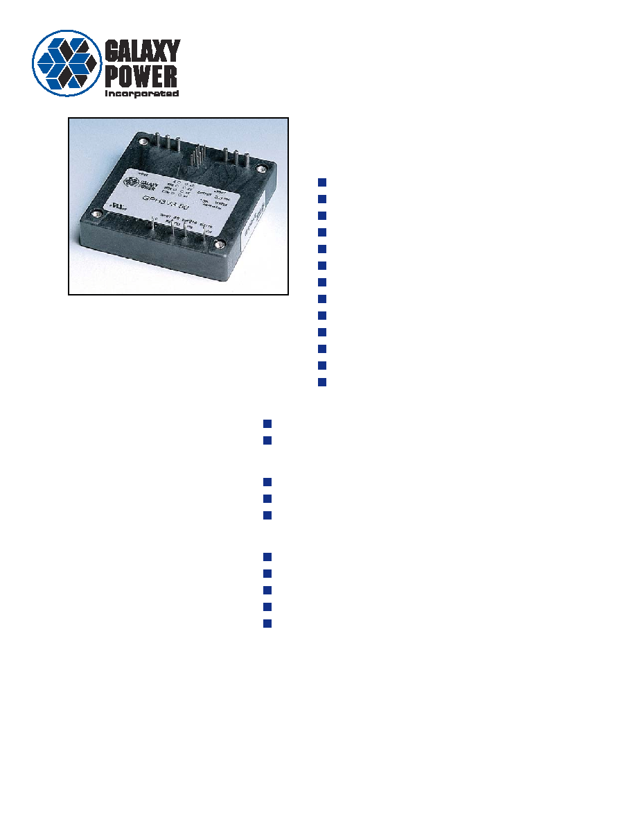
The Hercules Series are the highest
performance half brick DC/DC converters in
the industry with:
Output Current up to 60 Amperes
Parallel up to 5 units
Pin Programmable Output Voltage
200 Watts @ 100
∞ Baseplate
69 Watts/cu. inch
2.4" x 2.4" x 0.4"
Accurate Current Share
Synchronizable
Fixed Frequency Operation
Automatic OVP tracking to Voltage Trim
Output OK signal
UL and CSA approved
Two Year Warranty
HERCULES Series
Control Functions
Remote Sense
Output Enable
Protection Features
Over Temperature Protection
Over Voltage Protection
Over Current Protection
Typical Characteristics
Output Setpoint Accuracy:
±1.25%
Load & Line Regulation:
±0.25%
Noise & Ripple: 75 mVp≠p
Long Term Temperature Drift:
±0.5%
Output Trim
Industry's first 60A half brick DC/DC Converter
48V Input, 1.5V, 2.2V, 3.3V or 5.0V
Hercules Series, Page 2
Part No. 98≠002 Rev. 1.1
WWW.GALAXYPWR.COM
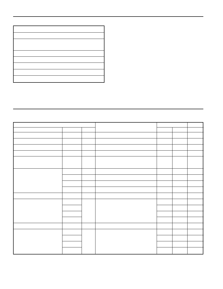
Input Characteristics
Baseplate Temperatures from 0
∞C to +100∞C.
Parameter
Test Condition
Requirement
Unit
Name
Var
Symbol
Min
Max
Input Voltage
V
I
36
72
V
Input Low Line Power On V
V
I
on
Module Power On
30
35
V
Input Low Line Power Off V
V
I
off
Module Shutdown
80
90
%V
I
on
No Load Input Power
P
IL
V
I
=V
I
nom
≠
2.5
W
Input Capacitor
rated 80V min
250
≠
µF
(external to the converter)
Input Current
1.5V
I
I
V
I
= 36V, I
O
= 60A, V
O
= 1.5V
≠
4.0
A
2.2V
I
I
V
I
= 36V, I
O
= 60A, V
O
= 2.2V
≠
5.2
A
3.3V
I
I
V
I
= 36V, I
O
= 50A, V
O
= 3.3V
≠
5.6
A
5.0V
I
I
V
I
= 36V, I
O
= 40A, V
O
= 5.0V
≠
6.3
A
Inrush Transient
V
I
= 48V, I
O
= I
O
max rated
≠
1.0
A
2
s
Efficiency
1.5V
V
O
= V
O
nom
, I
O
= I
O
rated
, V
I
=V
I
nom
66
≠
%
2.2V
74
≠
%
3.3V
77
≠
%
5.0V
80
≠
%
Reflected Input Ripple
V
I
= 48V, I
O
= Io max rated, C
I
= 250
µF
≠
2.5
A
p-p
Maximum Losses at
1.5V
P
d
V
I
= 48V, V
O
= V
O
nom
≠
44
W
Local Sense
2.2V
I
O
= I
O
max rated
, T
C
ase
= 70
∞C
≠
44
W
3.3V
≠
42
W
5.0V
≠
42
W
General Specifications
Operating Temperature
-20
∞C to +100∞C baseplate
Storage Temperature
≠40
∞C to +100∞C
Relative Humidity
10% to 95% RH,
Non≠condensing
Vibration
10≠500Hz 0.75g peak
Weight
130gm, maximum
Material Flammability
UL94V≠2
Safety
UL 1950, CSA C22.2 No. 950 approved
1
MTBF
MIL≠HDBK≠217
500,000 hours
2
Notes: 1. Requires one fuse located in either the plus or minus side of the 48V
supply; fuse rated for 7A max for all conditions.
2. 80% load; 70
∞C baseplate.
Specifications

Hercules Series, Page 3
Part No. 98≠002 Rev. 1.1
WWW.GALAXYPWR.COM
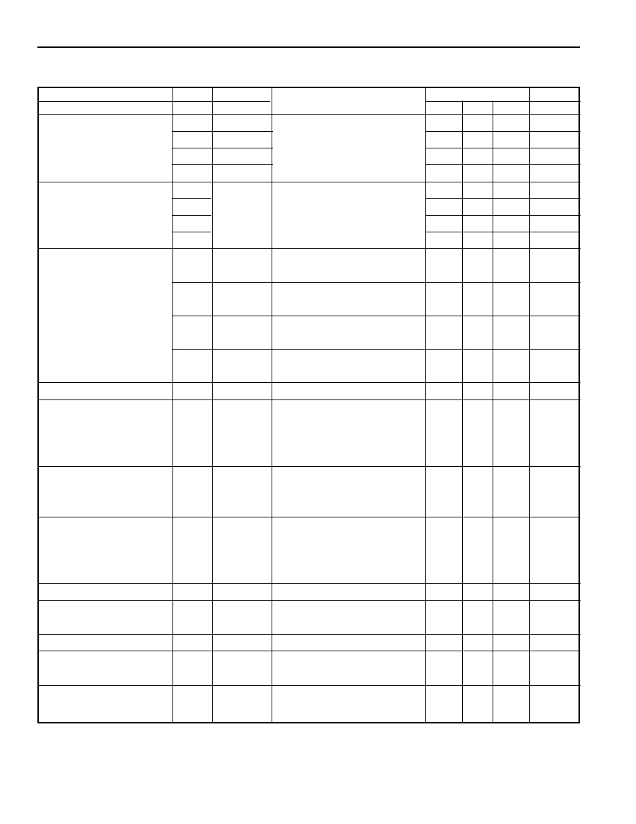
Output Characteristics
Over the complete baseplate temperatures and input voltage ranges.
Parameter
Test Condition
Requirement
Unit
Name
Var
Symbol
Min
Typ
Max
Output Voltage (nominal)
1.5V
V
O
nom
≠
1.5
≠
V
nom
2.2V
V
O
nom
≠
2.2
≠
V
nom
3.3V
V
O
nom
≠
3.3
≠
V
nom
5.0V
V
O
nom
≠
5.0
≠
V
nom
Rated Output Current
1.5V
I
O
V
O
= V
O
nom
0
≠
60/40
A
2.2V
I
O
V
O
= V
O
nom
0
≠
60/40
A
3.3V
I
O
V
O
= V
O
nom
0
≠
50/40
A
5.0V
I
O
V
O
= V
O
nom
0
≠
40/30
A
Initial Output Voltage
Vadj = open, T
C
= +25
∞C
-1.25
≠
1.25 %V
O
nom
Tolerance (with remote sense)
V
I
= V
I
nom
, I
O
= I
O
rated
/2
Noise and Ripple
20MHz
P
-
P
bandwidth,
75
mV
P
-
P
V
I
=36-72V, I
O
= 0 amps to 100%
Static Load and
V
I
=36-72V, I
O
= 0.2 amps to 100%
≠
≠
±0.25 %V
O
nom
Line Regulation
Long Term Temperature Drift
-0.5
_
0.5
%V
Voltage Programming
1.5V
V
IN
= 48V
V
adj
= 0.5V
≠
0.30
≠
mV/mV
Slope
V
O
= V
O
nom
to 1.5V
± 0.014
2.2V
I
O
= I
O
rated
/2
≠
0.44
≠
mV/mV
± 0.02
3.3V
≠
0.66
≠
mV/mV
± 0.03
5.0V
≠
1.0
≠
mV/mV
± 0.04
V
adj
Initial Tolerance
V
adj
= 1.0V
±1.25 %V
O
nom
Resistance Programming
R
adj
= 500
-11.7
-8.3
%V
O
nom
Tolerance
R
adj
= 1500
+8.3
+11.7 %V
O
nom
Total Remote Sense
1.5V
V
I
= V
I
min
, I
O
= I
O
max rated
≠
100
mV
Compensation (round trip)
2.2V
3.3V
≠
500
mV
5V
Output Overvoltage Protection
110
127
%V
O
(Latching)
prog.
Output Voltage Protection
T
OVP
V
O
= V
O
nom
, I
O
= I
O
rated
≠
30
µs
Response Time
Note: Overvoltage Protection must function over full programming range. Also, reference for OVP Threshold must be a redundant or equivalent reference.
Specifications
Hercules Series, Page 4
Part No. 98≠002 Rev. 1.1
WWW.GALAXYPWR.COM
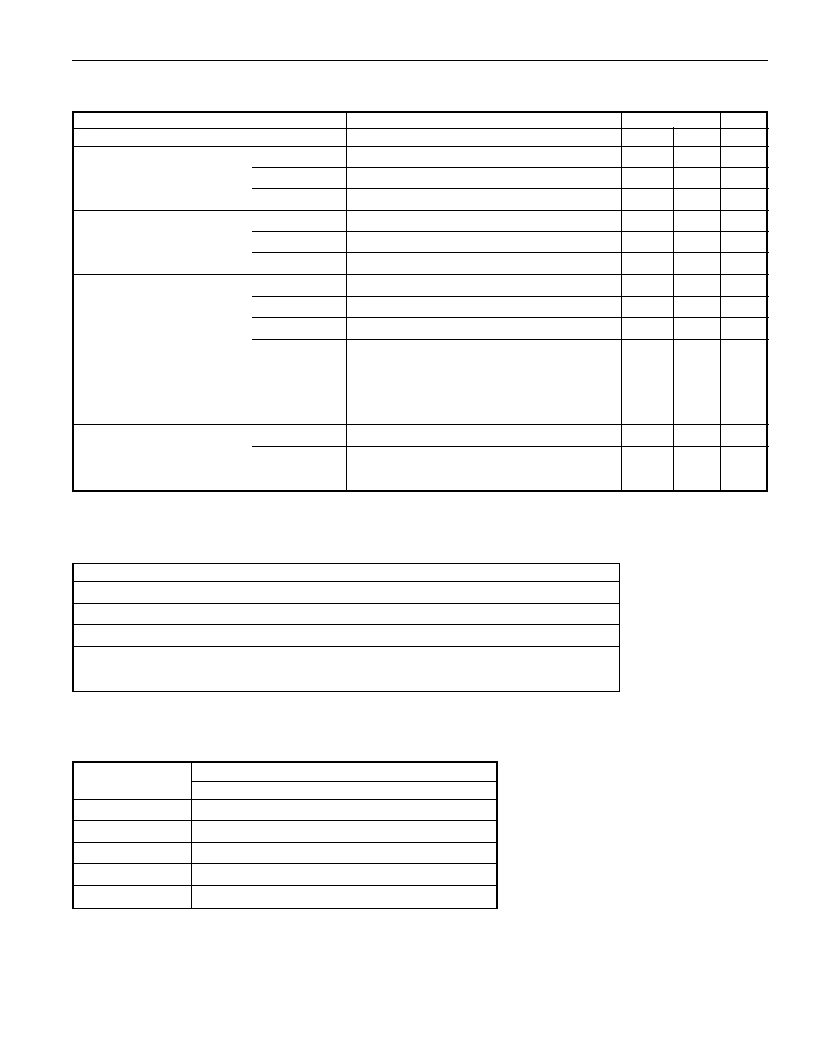
Output Characteristics (continued)
Over the complete baseplate temperatures and input voltage ranges.
Parameter
Test Condition
Requirement
Unit
Name
Var
Symbol
Min
Typ
Max
Current Limit (nominal)
1.5V
I
O
lim
V
O
= 90% V
O
nom
, V
I
= 48V
61
72
A
2.2V
I
O
lim
61
72
A
3.3V
I
O
lim
46
54
A
5.0V
I
O
lim
37
42
A
Short Circuit Current
1.5V
V
O
= 0.2 to 0.4V, V
I
= 72V
≠
≠
80/55
A
2.2V
≠
≠
80/55
A
3.3V
≠
≠
70/55
A
5.0V
≠
≠
55/45
A
Transient Response
1, 2
1.5V
I
step
=15A, di/dt=10A/
µsec
≠
≠
3
%V
O
nom
C
O
= 35-470
µf caps
2.2V
I
step
=28A, di/dt=28A/
µsec
≠
≠
3
%V
O
nom
C
O
= 35-470
µf caps
3.3V
I
step
=12A, di/dt=10A/
µsec
≠
≠
3
%V
O
nom
C
O
= 10-470
µf caps
5.0V
I
step
=10A, di/dt=10A/
µsec
≠
≠
3
%V
O
nom
C
O
= 5-470
µf caps
Settling Time to
±1%
≠
≠
600
µs
Turn On Time
t
on
I
O
= 5A, V
I
= V
I
min
to V
I
max
10
≠
75
ms
(to 90% final value)
C
in
= 250
µf, 80V
C
out
= 10,000
µf tantalum &
0.47
µf Ceramic
Rise Time (10% to 90%)
T
rise
V
I
= V
I
min
to V
I
max
10
≠
20
ms
I
O
= I
O
min
to I
O
max
Capacitors as in Turn On Time
Turn Off Time
t
off
I
O
= 5A, V
I
min
to V
I
max
≠
≠
2.0
ms
(to 10% initial value)
C
in
= 250
µf, 80V
Co = 330
µf tantalum &
0.47
µf Ceramic
External Load Capacitance
ESR@17,000
µf = 2m
1,500
18,800
µf
Current Sharing
Ishare
Vin = 48V, Vo = Vonom
--
±5
%I
O
max
(Secondary Side)
I = 10% Iop to Iop
Synchronization
Fanout
1
5
units
Over Temperature Shutdown
T
BASEPLATE
≠
≠
125
∞C
(Latching)
Isolation Resistance
10
M
(1500V
DC
) Input-Output
Notes: 1. Transient response is for a positive or a negative current step within the range of 5% of Imax to Imax.
2. Transient response is measured with the specified number of 470
µF tantalum external load capacitors with a maximum ESR of 55m each.
Specifications
Hercules Series, Page 5
Part No. 98≠002 Rev. 1.1
WWW.GALAXYPWR.COM
Specifications
Control Signal Characteristics
Parameter
Test Condition
Requirement
Unit
Name
Symbol
Min
Max
Enable_L
V
ENABLE
Enable_L asserted
0
0.8
V
Function Control
Enable_L de-asserted
4.5
5.5
V
Voltage (Secondary Side)
Source Current (V
ENABLE
= 0.8V)
≠
-1.0
mA
Enable
R
ENABLE
Enable_L asserted
≠
100
Function Control
Enable_L de-asserted
200K
≠
Resistance (Secondary Side)
Source Current (R
ENABLE
= 100
)
≠
-1.0
mA
OTW≠L
I
SINK
OTW_L asserted, V
S
= 5V, R
L
= 50
8
20
mA
Overtemperature Warning
I
LEAKAGE
OTW_L de-asserted, V
S
= 15V
≠
10
µA
V
L
OTW_L asserted, V
S
= 5V, R
L
=5K
≠
0.2
V
T
OTW
-
L
V
I
= 48V, V
O
= rated V
O
,
500
≠
ms
Time delay
I
O
= Rated I
O
max
, Fan-off early warning time
before converter shuts down due to thermal
overload
MODOK_L
I
LEAKAGE
MODOK_L de-asserted, V
S
= 15V
≠
10
µA
I
SINK
MODOK_L asserted, V
S
= 5V, R
L
= 50
8
20
mA
V
L
MODOK_L asserted, V
S
= 5V, R
L
= 5K
≠
0.2
V
Maximum Output Load Current (I
OP
) vs Number of Converters
No. of Converters
1.5V & 2.2V
3.3V
5.0V
1
60A
50A
40A
2
117A
87.75A
58.5A
3
174A
130.5A
87.0A
4
231A
173.25A
115.5A
5
288A
216A
144A
Thermal Characteristics (
CA
)
Air Velocity Thermal Resistance (Baseplate to Ambient)
∞
C/W
(m/s)
0.9" Heatsink
1.4" Heatsink
0.5
3.0
2.1
1.0
1.9
1.3
1.5
1.6
1.1
2.0
1.4
1.0
2.5
1.3
0.9

Hercules Series, Page 6
Part No. 98≠002 Rev. 1.1
WWW.GALAXYPWR.COM
Application Notes
Signal Characteristics: Per table on page 5.
Input Signals:
Enable_L: This input signal is used to enable the
output of the converter when activated (active Low).
The signal is referenced to the output side (≠Sense).
Enable_L does not require an external pull-up resistor.
If an external pull-up is used it should be tied to +5V.
To minimize start-up problems it is recommended that
Enable_L be driven from an open-drain configured FET.
Voltage Adjust: The output voltage of the converter
shall be adjustable as specified in the table on page 3.
The voltage adjust pin sources 1 mA current. The
adjustment shall be done using an external voltage
source or a resistor connected between the Voltage
Adjust pin and the ≠ Sense pin. See below for output
voltage adjustment application information.
Current Share: When two or more converters are
connected in parallel, their current share pins must be
connected together to allow proper load sharing.
Sync: When two or more converters from the same
manufacturer are connected in parallel, their sync pins
may be connected together to synchronize their
operating frequencies. When two or more converters
from different manufacturers are connected in parallel
their sync pins must NOT be connected together.
Output Signals:
MODOK_L: MODOK_L shall be asserted to indicate
that the output voltage is in regulation. When two or
more converters are operating in parallel a failed
converter may or may not de-assert its MODOK_L
signal.
OTW_L: OTW_L shall be asserted to indicate that the
converter temperature is too high and that the converter
is about to shut down. OTW_L will be asserted a
minimum of 500 msec before the converter shuts down
due to an overtemperature condition. The output of this
signal is the open drain of a FET. The output is current
limited to 8-15 mA and may be used to drive an external
LED directly.
Output Voltage Adjustment:
Voltage Programming: A voltage may be applied
between the Voltage Adjust pin (pin 5) and the ≠ Sense
pin (pin 1) to adjust the output voltage up or down from
the nominal output voltage by a maximum of
±10%.
The trim voltage for the GPH1V5-40 and GPH1V5-60
is:
(V
O
≠ 1.5)
V
TRIM
= ------------ + 1.0V
0.30
For the GPH2V2-40 and GPH2V2-60 the output voltage
may be trimmed to +15% , - 10%. The trim voltage for
these two units is:
(V
O
≠ 2.2)
V
TRIM
= ------------
+ 1.0V
0.44
The trim voltage for the GPH3V3-40 and GPH3V3-60 is:
(V
O
≠ 3.3)
V
TRIM
= ------------ + 1.0V
0.66
The trim voltage for the GPH5V0-30 and GPH5V0-40
is:
(V
O
≠ 5.0)
V
TRIM
= ------------ + 1.0V
1.0
Resistor Programming: A resistor may be connected
between the Voltage Adjust pin (pin 5) and the
≠ SENSE pin (pin 1) to adjust the output voltage up or
down from the nominal output voltage by a maximum
of +/- 10 %. The GPH2V2-40, -60 may be adjusted
+15 %, -10 %. The value of the trim resistor is for a
single converter or for multiple paralleled converters
with separate trim resistors on each of their Voltage
Adjust pins.
Although not recommended, the Voltage Adjust pins for
N paralleled converters may be tied together. In this
case the value of the trim resistor will be R
TRIM
/N.
For the GPH1V5-40 and GPH1V5-60, the trim resistor
value in Kohms for these two units is:
(V
O
≠ 1.5)
R
TRIM
= ------------ + 1.0K
0.30
The resistor value in Kohms for the GPH2V2-40 and
GPH2V2-60 is:
(V
O
≠ 2.2)
R
TRIM
= ------------ + 1.0K
0.44
The resistor value in Kohms for the GPH3V3-40 and
GPH3V3-60 is:
(V
O
≠ 3.3)
R
TRIM
= ------------ + 1.0K
0.66
Hercules Series, Page 7
Part No. 98≠002 Rev. 1.1
WWW.GALAXYPWR.COM
Output
DC/DC
Converter
R
LOAD
Input
+
≠
+
≠
P Enable
Case
In (+)
In (≠)
C3
1
µ
F
100V
C4
1
µ
F
100V
C2
1
µ
F
100V
C1
270
µ
F
63V
L1
Common Mode Inductor
C1
270
µ
F, 63V Aluminum Electrolytic Capacitor
C2-C4 1
µ
F, 100V Ceramic capacitor
48V RTN
48V
L1
80 UH
1
2
3
4
In (+)
In (≠)
∞
∞
+
The resistor value in Kohms for the GPH5V0-30 and
GPH5V0-40 is:
(V
O
≠ 5.0)
R
TRIM
= ------------ + 1.0K
1.0
Thermal Considerations:
Thermal considerations are an important factor in the
reliable operation of the converter. The maximum
operating baseplate temperature is 100
∞C. The
maximum recommended operating baseplate
temperature is 90
∞C. The baseplate temperature is a
function of the losses within the converter, the converter
ambient temperature, and airflow across the heat sink.
The reference baseplate temperature is measured at the
center coordinates of the baseplate.
The baseplate temperature can be approximated by the
following equation:
1 ≠
T
BASEPLATE
= P
OUTPUT
*----------*R
BASEPLATE
-
AMBIENT
+ T
AMBIENT
Where:
T
BASEPLATE
is the temperature of the baseplate.
T
AMBIENT
is the local ambient temperature around the
converter
is the efficiency of the converter (see table on page
2)
R
BASEPLATE
-
AMBIENT
is the thermal resistance from the
baseplate to the ambient environment. This is a
function of the heat sink and air velocity. See table
on page 5 for thermal resistance characteristics.
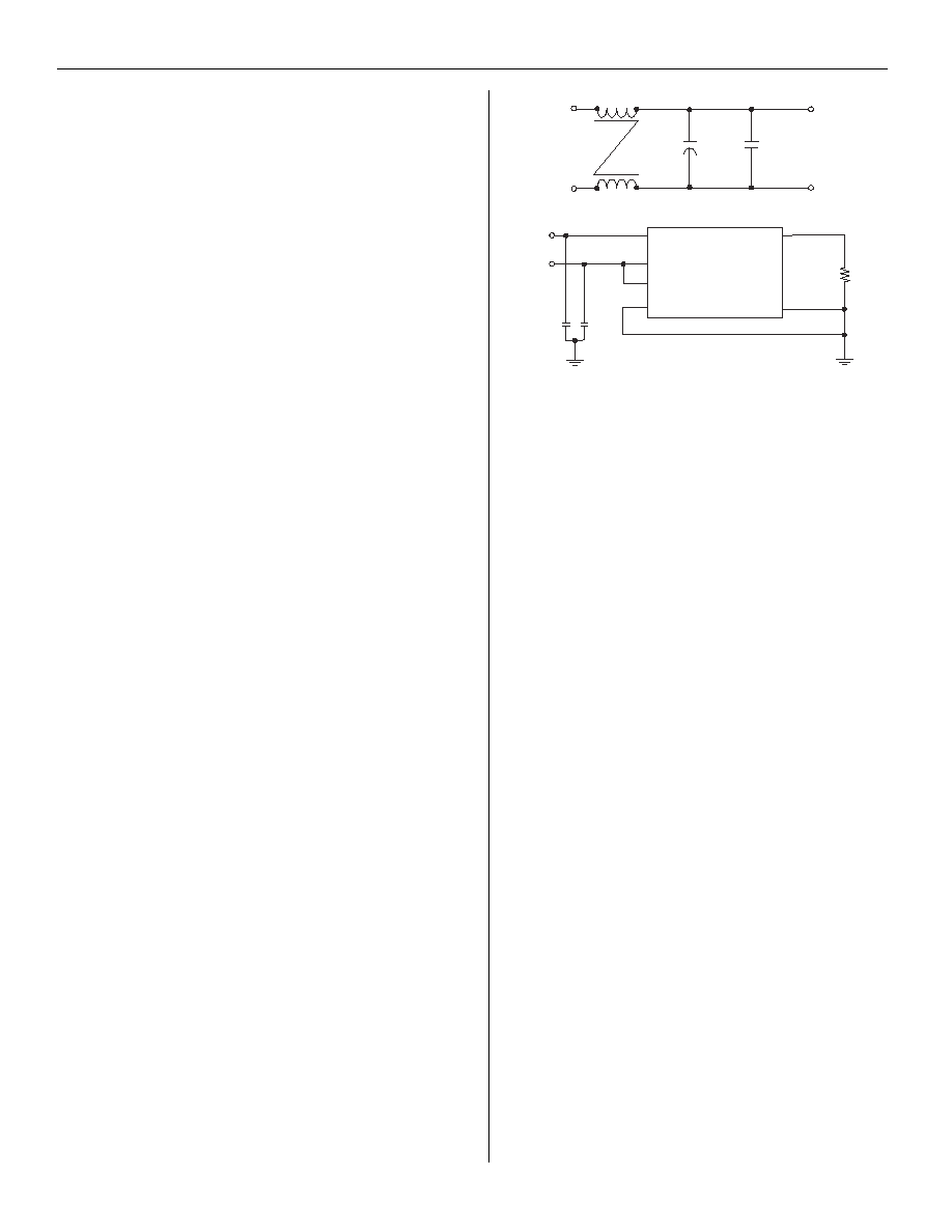
Recommended Input Filter, Fuse and Case
Connections: A fuse is required in series with the plus
or minus side of the 48V input to meet safety
requirements. The following input filter circuit is
recommended for all applications. The fuse should be
inserted between the capacitors and the plus or minus
input of the converter. The case should be connected to
the output return.
Application Notes
Paralleling Converters: Two to five converters can be
paralleled as long as the following conditions are met.
When all of the converters are from the same
manufacturer the current share pins must be connected
together and the sync pins may be connected together if
desired.
When converters from different manufacturers are
paralleled, the current share pins must be connected
together and the sync pins must NOT be connected
together.
The maximum output current for paralleled
configurations is shown in the table on page 5.
When a converter fails in a parallel configuration it may
or may not deassert its MODOK_L signal.
It should also be noted that current for the control
circuit in the converter flows through the ≠ SENSE lead.
For this reason it is important to keep the impedance
between the ≠ SENSE pins on the converters in a
parallel configuration low. The best approach is to
connect the ≠ SENSE pins together with as large of an
etch as possible (250 milliohms maximum
recommended) and then run a single set of sense leads
to the remote sense point at the load.

Hercules Series, Page 8
Part No. 98≠002 Rev. 1.1
WWW.GALAXYPWR.COM
155 Flanders Road Westborough, MA 01581
508≠870≠9775 Fax: 508≠870≠9796
e≠mail: galaxy@galaxypwr.com
website: http://www.galaxypwr.com
© Copyright 2000 Galaxy Power. Specifications subject to change without notice.
ORDERING INFORMATION
Model
Output
Max
Efficiency
Number
Voltage
Current
(Typ)
GPH5V0-40
5.0V
40 A
85%
GPH5V0-30
5.0V
30 A
86%
GPH3V3-50
3.3V
50 A
81%
GPH3V3-40
3.3V
40 A
82%
* Heatsinks required: available on request. See table on page 5.
PACKAGE DETAIL
J1
2.400 Max
2.400 Max
4
5
1
8
0.200 Ref
0.555
Max
Converter
0.175
0.300
0.100
2.000
1.450
1.750
1.250
1.900
0.925
1.500
1.325
1.150
0.700
0.350
0.175
0.240
Bottom View (facing pins)
≠V
OUT
≠V
OUT
≠V
OUT
+V
OUT
+V
OUT
+V
OUT
Case
N/C
≠V
IN
+V
IN
Recessed M3 Insert,
0.5 inches long
(optionsl) 4plcs
Heatsink Profile
Indicates
Pin 1
Notes:
1. General Tolerance:
.XX = 0.02
.XXX = 0.005
2. Tolerance for 0.040 and
0.080 pins to be 0.002
3. Use 4-40 screws to
mount heatsink
4. Bottom surface must be
insulated (primary and/or
secondary etch may run
underneath case)
Pin Assignments
Power Pins
Designation
Pin Config.
+Vout
.080 round
≠Vout
.080 round
Case
.040 round
N/C
.040 round
≠Vin
.040 round
+Vin
.040 round
Signal Pins (25 mils sq.)
Pin
Designation
1
-Sense
2
SYNC
3
MODOK_L
4
OTW_L
5
Voltage Adjust
6
Enable_L
7
Current Share
8
+ Sense
Model
Output
Max
Efficiency
Number
Voltage
Current
(Typ)
GPH2V2-60
2.2V
60 A
74%
GPH2V2-40
2.2V
40 A
75%
GPH1V5-60
1.5V
60 A
67%
GPH1V5-40
1.5V
40 A
68%
Galaxy Power Inc. warrants to the original purchaser that
the products conform to this data sheet and are free from
material and workmanship defects for a period of two (2)
years from the date of manufacture, if this product is used
within specified conditions. Galaxy Power Inc. reserves
the right to make changes to the product(s) or information
contained herein without notice. No liability is assumed as
a result of their use or application. No rights under any
patent accompany the sale of any such products or
information. For additional details on this limited warranty
consult the factory.