Leo Series, Page 1
PRELIMINARY
Part No. 99≠001 Rev. 4.0≠120902
The Leo is a 3/4 brick
CoolConverter
TM
in the Galaxy family of high-efficiency
DC/DC converters.
Typical Efficiency:
91% at 1.8V, 60A; 88% at 1.8V, 120A
Highest Ripple Frequency, 600kHz,
for Low EMI
Industry Compatible Footprint
Democratic Secondary-side Current Sharing
Ultra High Initial Setpoint Accuracy,
±0.2%
Wide Trim Range, +10 to -70%
Single Pole Transient Response (No Ringing)
Rapid Turn-on from Valid Input Voltage
Two Year Warranty
LEO Series
Industry's Highest Current DC/DC Converter.
48V or 24V Input, 250W, 120A Output,
3.3V 90A, 2.5V 100A, 1.8V 120A, 1.5V 120A, 1.2V 120A
standard with extra wide trim range
Control Functions
Uses Patented Power Supply Control
and Architecture
Primary/Secondary Microprocessor
Controlled
Three Enable Signals Standard for
Maximum Flexibility
Differential Remote Sense
Active High Power-Good Signal
The open frame 3/4 brick Leo
is also available with an optional heatsink.
Protection Features
Over Temperature Protection
Over Voltage Protection
Under Voltage Lockout
Delayed Lockout for Over Input Voltage
Continuous Constant Current Limit
Typical Characteristics
Output Setpoint Accuracy:
±0.2%
Load Regulation:
±0.25%
Line Regulation:
±0.25%
Regulation over Line, Load, and
Temperature:
±1%
Leo Series, Page 2
PRELIMINARY
Part No. 99≠001 Rev. 4.0≠120902
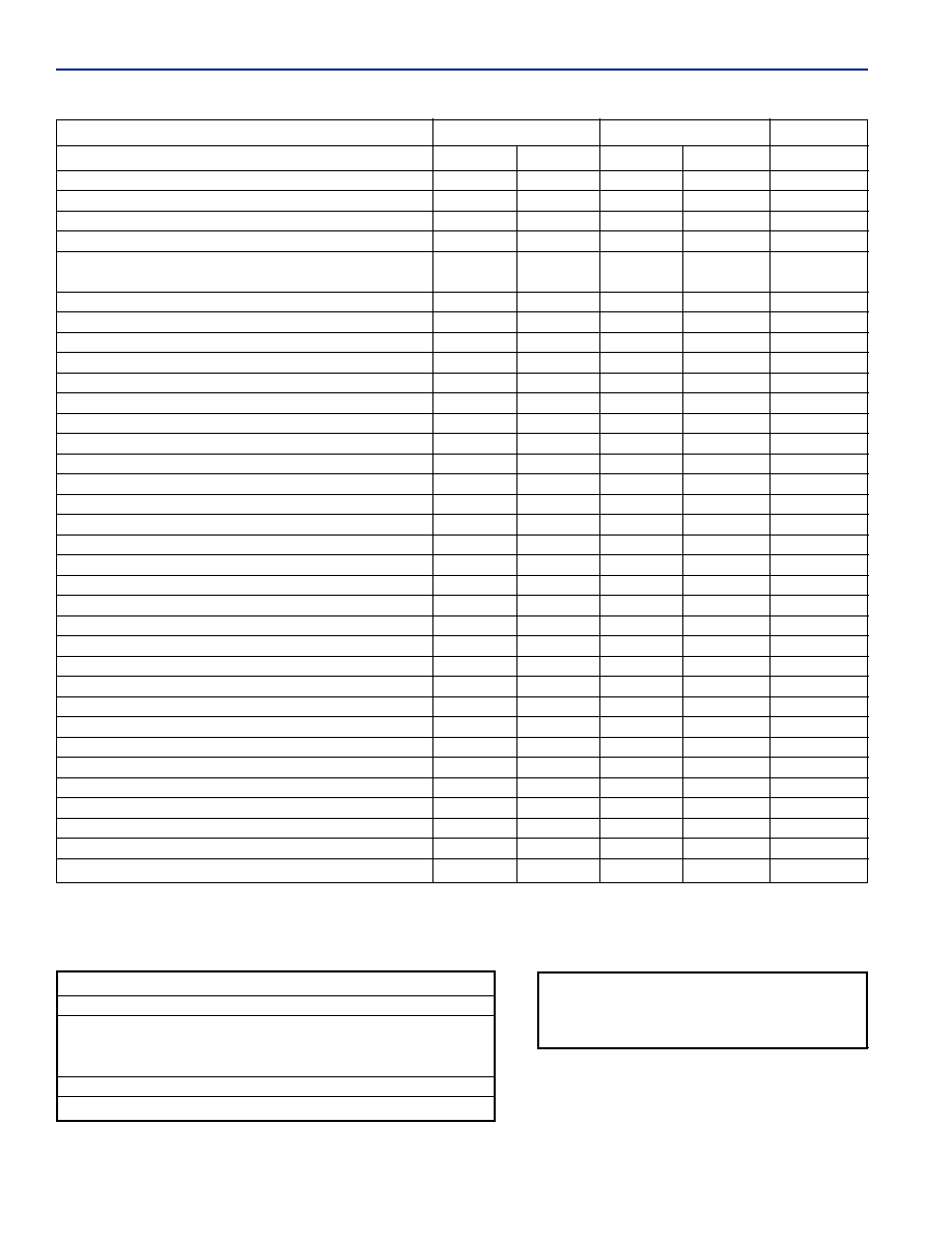
General Specifications
V
IN
= 48V
DC
, T
A
@25
∞C, 300 LFM airflow, V
OUT
= rated output voltage , I
OUT
= Full Load unless otherwise noted.
Available output power depends on ambient temperature and good thermal management. (See application graphs for limits.)
Input Characteristics
48V Series
24V Series
Parameter
Min
Max
Min
Max
Units
Operating Input Voltage
35.5
75.5
17.5
36.5
V
DC
Input Current (Model Dependent)
8.6
17
A
Input Capacitance
6.6
20
µF
Input Hysteresis, Low Line
1
3
1
3
V
DC
Reflected Input Ripple
1.5
20
mA
RMS
through 10
µH with 47µF on input
Control Signal Low Input Voltage
1
1
1
V
DC
Control Signal High Input Voltage
4
4
V
DC
Maximum Input Voltage, non-operating
100
100
V
DC
No Load Input Current
70
100
mA
Output Characteristics
Output Voltage, half-load, 48Vin, 25
∞C
99.8
100.2
99.8
100.2
%V
NOM
Regulation Over Line, Load & Temperature
99
101
99
101
%V
NOM
Voltage Ripple
5V
50
50
mV
P-P
5V
12
12
mV
RMS
3.3V
35
35
mV
P-P
3.3V
9
9
mV
RMS
Current Range
5V
0
60
0
45
A
DC
3.3V
0
90
0
85
A
DC
2.5V
0
100
0
100
A
DC
1.8V
0
120
0
120
A
DC
Short Circuit
105
125
105
125
%I
MAX
Trim Range
-70
+10
-70
+10
%V
NOM
Overvoltage Protection, Tracking, Latching
125
135
125
135
%V
SET
Overvoltage Protection, Redundant, Latching
135
140
135
140
%V
NOM
Isolation
Isolation Test Voltage, Input/Output (Basic)
2250
2250
V
DC
Isolation Resistance
10
10
M
Features
Over-temperature Protection, Thermal Sensor
2
120
125
120
125
∞C
Input-output Capacitance
2200
2200
pF
Isense Signal, no load to current limit
0
2.5
0
2.5
V
DC
Ishare Accuracy (See application notes)
95
105
95
105
%
Power Good Range
95
105
95
105
%V
SET
Power Good High Level
4.75
5.25
4.75
5.25
V
DC
Notes: 1. Internal pull up on both Control_L Primary and Secondary and Control_H pins are provided which source <0.2mA. For the module
to operate Control_L needs to be low with respect to Vin(-) and Control_H needs to be high, or open-circuited.
2. PCB less than 130
∞C.
General Specifications
Operating Temperature
-40
∞C to +100∞C
Storage Temperature
≠55
∞C to +125∞C
Relative Humidity
10% to 95% RH,Non-condensing
Vibration
2 to 9Hz, 3mm disp., 9 to 200Hz1g
Material Flammability
UL V-0
Weight (open frame)
55 grams
MTBF Telcordia (Bellcore)
1,600,000 hours
Approvals and Standards
UL and c-UL Recognized Component,
TUV pending, UL60950, CSA 22.2 No. 950,
IEC/EN60950**
** An external fuse shall be used to comply with the requirements.
Leo Series, Page 3
PRELIMINARY
Part No. 99≠001 Rev. 4.0≠120902
CoolConverter
TM
Family
Galaxy's
C
OOL
C
ONVERTER
TM
Family features:
∑ Patented single-stage power conversion architecture, control,
and magnetic design allow unprecedented power density and
efficiency in an isolated power supply.
∑ An advanced microcontroller reduces parts count while
adding features, performance, and flexibility in the design.
∑ Low common-mode noise as a result of lower capacitance in
the transformer compared to planar magnetics and metal
baseplate designs.
∑ Higher reliability than planar transformer designs that can
suffer from via fatigue from thermal cycling, and metal
baseplate designs with board to board interconnects that are
subject to mechanical stress on electrical connections.
Application Notes
Protection and Control
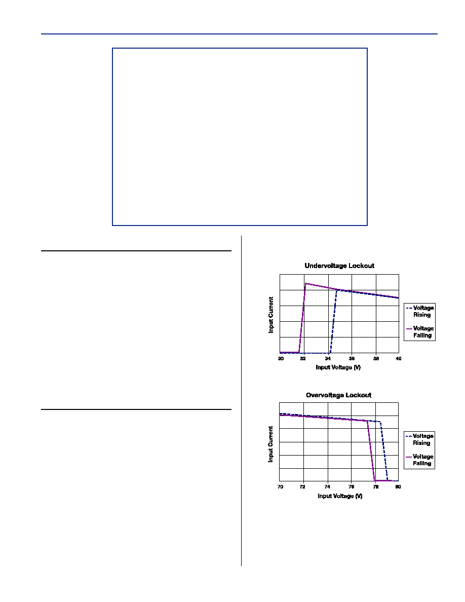
Valid Input Voltage Range:
The converter measures the input voltage and will
not allow operation outside of the input voltage
specification. As shown by the graphs, hysteresis is
added to both the high and low voltage to prevent
the converter from turning on and off repeatedly
when the voltage is held near either voltage
extreme. At low line this assures the maximum
input current is not exceeded; at high line this
assures the semiconductor devices in the converter
are not damaged by excessive voltage stress. Shut
down for over-input voltages is inhibited for 100 ms
transients to prevent false shut down due to
transient input voltage conditions.
ON/OFF Logic:
The Leo family of converters comes standard
with both positive and negative logic input-side
shutdown pins and positive logic secondary-side
shutdown. All enable pins have internal pull-ups of
approximately 0.2mA. The secondary-side enable
allows for system sequencing without the need for
an opto-isolator. For the converter to operate all
negative logic enable inputs must be less than one
volt and the positive logic enable must be greater
than 4V or open-circuited.
Leo Series, Page 4
PRELIMINARY
Part No. 99≠001 Rev. 4.0≠120902
APPLICATION NOTES
Output Over Voltage Protection:
The output voltage is monitored in two ways, by
the microcontroller which looks at the sensed signal
and a high-speed comparator that measures the
power pins. The microcontroller OVP allows the
OVP circuit to track the trimmed signal. However,
this circuit does not allow OVP signal detection in
the event the voltage sense pins are shorted
together. In that case, a redundant OVP set at a
fixed threshold will prevent excessive voltage.
Thermal shutdown:
The printed circuit board temperature is measured
using a semiconductor sensor. If the maximum
rated temperature is exceeded, the converter is
shutdown until the temperature decreases to 90
degC. The time for this depends on the airflow and
heatsink mass.
Please consult Galaxy Power for your special
needs.
Remote Sense:
The output voltage is regulated at the point where
the sense pins connect to the power output pins.
Total sense compensation should not exceed 0.4V
or 10% of Vout, whichever is greater.
If the unit is trimmed up, the application requires
that, under all conditions including current
transients, the output voltage must be kept less than
the redundant OVP, otherwise the unit will
shutdown.
Safety:
An external input fuse must always be used to
meet these safety requirements.
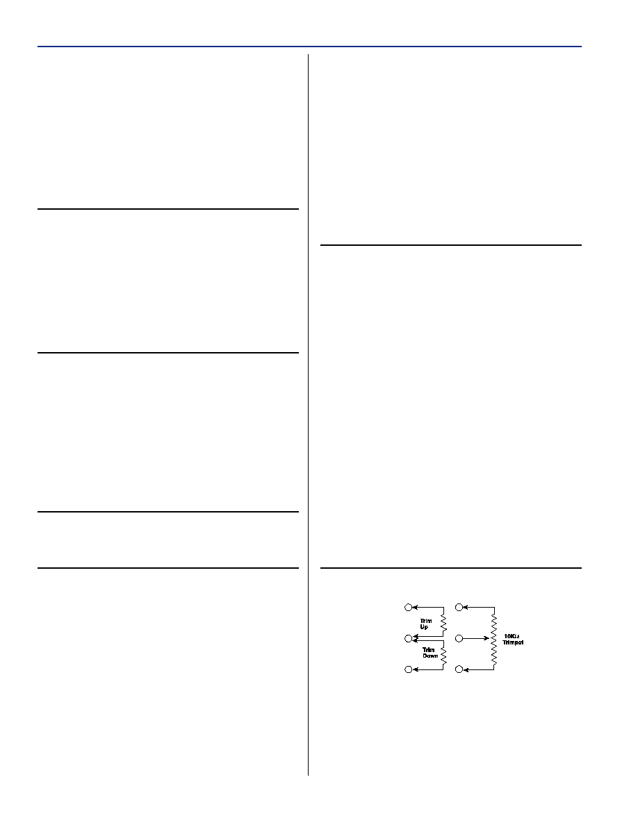
Trim:
The Leo converter has a novel regulation circuit
that uses a differential measurement technique to
eliminate voltage sense current. To trim the unit up,
a resistor is connected from the trim pin to the
Negative Sense pin. To trim the unit down, a
resistor is connected from the trim pin to the
Positive Sense pin. All models follow these trim
equations:
R
TRIM DOWN
=
2250/D ≠ 30k
R
TRIM UP
=
750/Dk
where D is the percentage of trim (i.e. 10 = 10%).
For example, to trim up 10%, a 75k
resistor
External Output Trimming
would be connected from the trim pin to the
Negative Sense Pin.
Power Good Signal
The Leo generates a power good signal when the
output voltage falls in a 5% window of the nominal
value. The circuit tracks the trimmed voltage. The
circuit has a response time of approximately 1ms.
The output signal is derived from an internal 5V
power bus and can source up to 5mA. If interfacing
to other logic is required, the output can drive a
resistor divider to set a new high level. The voltage
is referenced to the V
O
(-) pin.
Transient Response and Stability
The Leo uses a high-bandwidth control to keep
the output voltage in regulation. The crossover
frequency of the Leo is approximately 15kHz
(depending on the model) with greater than 60
degrees of phase margin. The control circuit
maintains high phase margin at lower frequencies
allowing the use of large amounts of external
capacitance to be applies without loss of stability.
If you require a high di/dt solution, Galaxy can
adjust the gain of the control to take advantage of
the on-board capacitance and improve the transient
performance up to 5X the nominal value.
If several Leos are used in parallel with current
sharing, the transient response is improved by the
number of Leos. For example, with two Leos a
60A step will give the same response as a single
Leo with a 30A step, or about 1/2 the peak
over/undershoot.
+ Sense
Trim
≠ Sense

Leo Series, Page 5
PRELIMINARY
Part No. 99≠001 Rev. 4.0≠120902
Efficiency
GPLW1V5120
94
92
90
88
86
84
82
80
0
20
40
60
80
100
120
Load Current (A)
Ef
ficiency (%)
36V Vin
48V Vin
60V Vin
Efficiency
GPLW2V5100
94
92
90
88
86
84
82
80
0
20
40
60
80
100
Load Current (A)
Ef
ficiency (%)
36V Vin
48V Vin
60V Vin
Efficiency
GPLW3V3090
94
92
90
88
86
84
82
80
0
20
40
60
80
Load Current (A)
Ef
ficiency (%)
36V Vin
48V Vin
60V Vin
36V Vin
48V Vin
60V Vin
20
60
40
80
100
120
45
40
35
30
25
20
15
10
5
0
GPLW1V5120
36V Vin
48V Vin
60V Vin
20
100
60
40
80
35
30
25
20
15
10
5
0
GPLW2V5100
36V Vin
48V Vin
60V Vin
20
60
40
80
35
30
25
20
15
10
5
0
GPLW3V3090
Leo Series OPERATION