 | –≠–ª–µ–∫—Ç—Ä–æ–Ω–Ω—ã–π –∫–æ–º–ø–æ–Ω–µ–Ω—Ç: GPP1V5-25 | –°–∫–∞—á–∞—Ç—å:  PDF PDF  ZIP ZIP |
Polaris Series, Page 1
Part No. 99≠003 Rev. 1.0
WWW.GALAXYPWR.COM
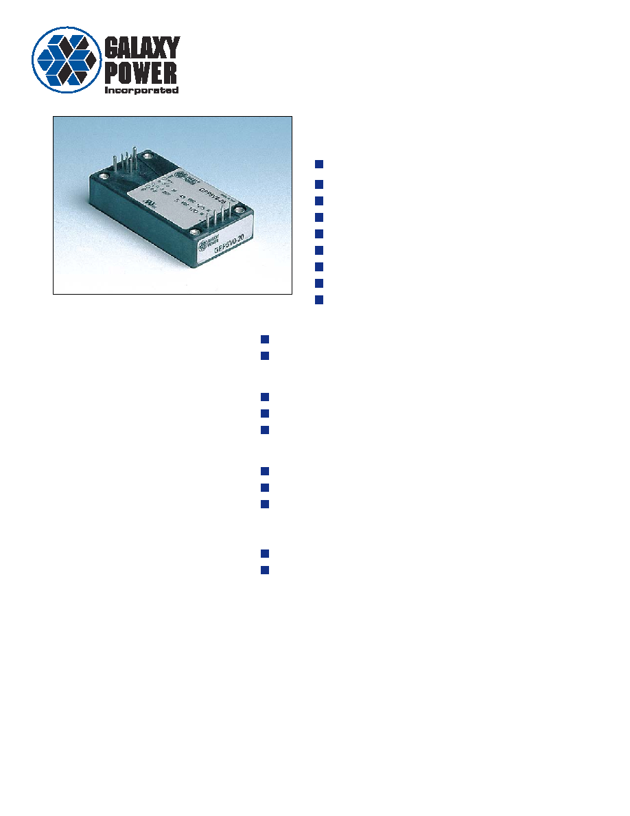
The Polaris Series is a high current 100W
quarter brick DC/DC converter with:
100 Watts @ 100
∞ Baseplate
67 Watts/cu. inch
1.2" x 2.4" x 0.5"
Fixed Frequency Operation
Remote Sense
Output Voltage Trim
Optional Heatsink
UL and CSA approved
Two Year Warranty
Polaris Series
Control Functions
Remote Sense
Primary and Secondary Output Enable
Protection Features
Over Temperature Protection
Over Voltage Protection
Over Current Protection
Typical Characteristics
Output Setpoint Accuracy:
±1.25%
Load & Line Regulation:
±0.25%
Noise & Ripple:
75 mVp≠p (1.5, 2.2V)
100 mVp≠p (3.3, 5.0V)
Long Term Temperature Drift:
±0.5%
Output Trim
The only true "quarter brick" on the market
48V Input, 1.5V, 2.2V, 3.3V, or 5.0V
Polaris Series, Page 2
Part No. 99≠003 Rev. 1.0
WWW.GALAXYPWR.COM
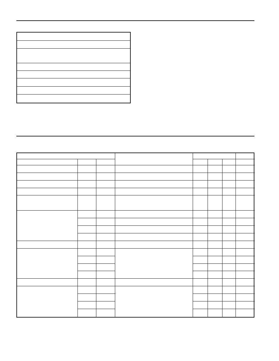
Input Characteristics
Baseplate Temperatures from 0
∞C to +100∞C.
Parameter
Test Condition
Requirement
Unit
Name
Var
Symbol
Min
Typ
Max
Input Voltage
V
I
36
72
V
Input Low Line Power On V
V
I
on
Module Power On
30
35
V
Input Low Line Power Off V
V
I
off
Module Shutdown
80
90
%V
I
on
No Load Input Power
P
IL
V
I
=V
I
nom
≠
2.0
W
Input Capacitor
rated 80V min
100
≠
µF
(external to the converter)
Input Current
1.5V
I
I
V
I
= 36V, I
O
= 24A, V
O
= 1.5V
≠
1.5
A
2.2V
I
I
V
I
= 36V, I
O
= 24A, V
O
= 2.2V
≠
2.1
A
3.3V
I
I
V
I
= 36V, I
O
= 24A, V
O
= 3.3V
≠
3.0
A
5.0V
I
I
V
I
= 36V, I
O
= 16A, V
O
= 5.0V
≠
3.0
A
Inrush Transient
≠
0.5
A
2
s
Efficiency
1.5V
V
O
= V
O
nom
, I
O
= I
O
rated
, V
I
=V
I
nom
68
70
≠
%
2.2V
72
74
≠
%
3.3V
78
80
≠
%
5.0V
82
84
≠
%
Reflected Input Ripple
V
I
= 48V, I
O
= 24A
≠
2.5
A
p-p
Maximum Losses at
1.5V
P
d
V
I
= 48V, V
O
= V
O
nom
≠
17.0
W
Local Sense
2.2V
P
d
I
O
= I
O
max rated
, T
C
ase
= 70
∞C
≠
20.6
W
3.3V
P
d
≠
22.4
W
5.0V
P
d
≠
17.6
W
General Specifications
Operating Temperature
0
∞C to +100∞C baseplate
Storage Temperature
≠40
∞C to +100∞C
Relative Humidity
10% to 95% RH,
Non≠condensing
Vibration
10≠500Hz 0.75g peak
Weight
80gm, max. without heatsink
Material Flammability
UL94V≠2
Safety
UL 1950, CSA C22.2 No. 950 approved
1
MTBF
MIL≠HDBK≠217
1,000,000 hours
2
Notes: 1. Requires one fuse located in either the plus or minus side of the 48V
supply; fuse rated for 8A max for all conditions.
2. 50-100% load; 40
∞C baseplate.
Specifications
Polaris Series, Page 3
Part No. 99≠003 Rev. 1.0
WWW.GALAXYPWR.COM
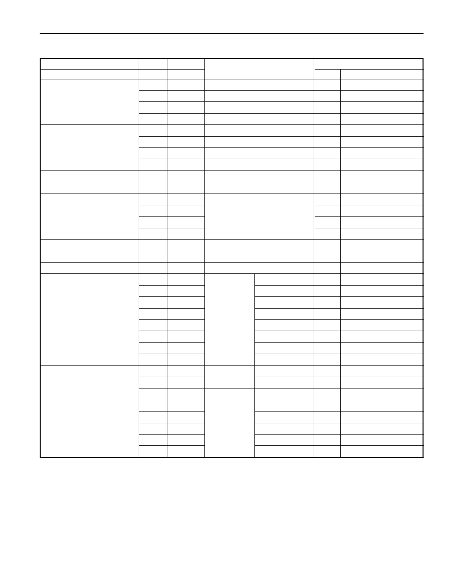
Output Characteristics
Over the complete baseplate temperatures and input voltage ranges.
Parameter
Test Condition
Requirement
Unit
Name
Var
Symbol
Min
Typ
Max
Output Voltage (nominal)
1.5V
V
O
nom
≠
1.5
≠
V
2.2V
V
O
nom
≠
2.2
≠
V
3.3V
V
O
nom
≠
3.3
≠
V
5.0V
V
O
nom
≠
5.0
≠
V
Rated Output Current
1.5V
I
O
V
O
= V
O
nom
0
≠
25
A
2.2V
I
O
V
O
= V
O
nom
0
≠
25
A
3.3V
I
O
V
O
= V
O
nom
0
≠
25
A
5.0V
I
O
V
O
= V
O
nom
0
≠
20
A
Initial Output Voltage
Vadj = open, T
C
= +25
∞C
-1.25
≠
1.25
%V
O
nom
Tolerance (with remote sense)
V
I
= V
I
nom
, I
O
= I
O
rated
Noise and Ripple
1.5V
20MHz
P
-
P
bandwidth,
≠
75
mV
P
-
P
2.2V
V
I
=36-72V, I
O
= 0 amps to 100%
≠
75
mV
P
-
P
3.3V
≠
100
mV
P
-
P
5.0V
≠
100
mV
P
-
P
Static Load and
V
I
=36-72V, I
O
= 0.2amps to 100%
≠
≠
0.25
%V
O
nom
Line Regulation
Long Term Temperature Drift
-0.5
≠
0.5
%V
Output Voltage Trim
1.5V
V
O
trim
V
IN
= 48V
Rtrim=13200
1.683
≠
1.717
V
V
O
= V
O
nom
Rtrim=42200
1.336
≠
1.363
V
2.2V
V
O
trim
Rtrim=140768
2.287
≠
2.333
V
Rtrim=8250
1.683
≠
1.717
V
3.3V
V
O
trim
Rtrim=41905
3.430
≠
3.500
V
Rtrim=122825
3.103
≠
3.166
V
5.0V
V
O
trim
Rtrim=118000
5.197
≠
5.303
V
Rtrim=105511
4.703
≠
4.798
V
Output Voltage Trim
1.5V
V
O
trim
I
O
= 50%
Vtrim=1.404
1.683
≠
1.717
V
of I
O
max
Vtrim=0.700
1.336
≠
1.363
V
2.2V
V
O
trim
Vtrim=1.149
2.287
≠
2.333
V
Vtrim=0.313
1.683
≠
1.717
V
3.3V
V
O
trim
Vtrim=2.808
3.430
≠
3.500
V
Vtrim=2.156
3.103
≠
3.166
V
5.0V
V
O
trim
Vtrim=2.869
5.197
≠
5.303
V
Vtrim=2.130
4.703
≠
4.798
V
Specifications

Polaris Series, Page 4
Part No. 99≠003 Rev. 1.0
WWW.GALAXYPWR.COM
Output Characteristics (continued)
Over the complete baseplate temperatures and input voltage ranges. Airflow adjusted at 500LFM with 0.9" high heatsink.
Parameter
Test Condition
Requirement
Unit
Name
Var
Symbol
Min
Typ
Max
Total Remote Sense
V
I
= V
I
min
, I
O
= I
O
max rated
≠
≠
100
mV
Compensation (round trip)
Output Overvoltage
1.5V
2.00
≠
2.30
V
Protection (Latching)
2.2V
2.64
≠
2.86
V
3.3V
3.96
≠
4.29
V
5.0V
6.00
≠
6.50
V
Output Voltage Protection
T
OVP
V
O
= V
O
nom
, I
O
= I
O
rated
≠
≠
150
µs
Response Time
Current Limit (nominal)
1.5V
I
O
lim
V
O
= V
O
nom
, V
I
= 48V
27
≠
≠
A
2.2V
I
O
lim
27
≠
≠
A
3.3V
I
O
lim
27
≠
≠
A
5.0V
I
O
lim
22
≠
≠
A
Short Circuit Current
1.5V
V
O
= 0.2 to 0.4V, V
I
= 72V
≠
≠
38
A
Transient Response, Vo
Io = 25≠75% Imax @ 0.1A/
µsec
≠
≠
150
mV
Deviation from Steady State
(di/dt), positive or negative step
1
Settling Time (to
±1%)
≠
≠
250
µs
Turn On Time
t
on
V
I
min
to V
I
max
1
≠
20
ms
Turn on Ramp Time
t
ramp
V
I
min
to V
I
max
, 10-90% rise time
1
≠
10
ms
Turn Off Time
t
off
V
I
min
to V
I
max
≠
≠
1.0
ms
(to 10% initial value)
External Load Capacitance
ESR@10,000
µf = 2m
100
10,000
µf
Over Temperature Shutdown
T
BASEPLATE
≠
≠
125
∞C
(Latching)
Isolation Resistance
10
≠
M
(1500V
DC
) Input-Output
Notes: 1. 940
µf (2, 470µF tantalum capacitor) solid tantalum capacitor placed across output.
Specifications

Polaris Series, Page 5
Part No. 99≠003 Rev. 1.0
WWW.GALAXYPWR.COM
Specifications
Control Signal Characteristics
Parameter
Test Condition
Requirement
Unit
Name
Symbol
Min
Max
P_Enable_L and
V
ENABLE
LOW
Module Enabled
0
0.8
V
S_Enable_L
V
ENABLE
HIGH
Module Disabled
2.5
6.0
V
Function Controls
I
ENABLE
LOW
Source Current (V
ENABLE
= 0.8V)
≠
-1.0
mA
P_Enable_L and
R
ENABLE
LOW
Module Enabled
≠
100
S_Enable_L
R
ENABLE
LOW
Module Disabled
200K
≠
K
Function Controls
I
ENABLE
LOW
Source Current (R
ENABLE
= 100
)
≠
-0.5
mA
Enable Controls
Primary Enable_L
Secondary Enable_L
Output Voltage
Low
Low
On
High or Open
Low
Off
Low
High or Open
Off
High or Open
High or Open
Off
To V
ENABLE
Pin
2N7000
or
Equivalent
.22
µ
F
Tantalum
IN4148
220K
1M
To (≠)
On >3V
Off
0.6V
Enable Circuit
Turn on Time
Output Load Conditions
(Turn On)
V
ENABLE
0.8V
Turn on Time for
V
ENABLE
going Low
Time
V
OUT
T
ON
Time
Regulation Band
3V
Turn on Time
V
ENABLE
2.5V
Turn off Time for
V
ENABLE
going High
Time
Input
Current
T
OFF
Time
90% of Initial
Input Current
Output Voltage
Turn off Time

Polaris Series, Page 6
Part No. 99≠003 Rev. 1.0
WWW.GALAXYPWR.COM
Application Notes
Signal Characteristics: Per table on page 5.
Input Signals:
Enable_L: This unit has both primary and secondary
output enable:
Primary Enable_L: This input signal is used to enable
the output of the converter when activated (active Low).
The signal is referenced to the input side (-Vin pin 11).
Secondary Enable_L: This input signal is used to
enable the output of the converter when activated (active
Low). The signal is referenced to the output side
(-Sense).
Output Voltage Adjust: The output voltage of the
converter can be adjusted above or below the nominal
output voltage as specified in the Output Characteristics
Table. The range of adjustment above the nominal
output voltage is limited by the internal overvoltage trip
point settings. The overvoltage trip point settings do
not change with output voltage adjustments.
Output Voltage Turn On Time: The external circuit
used to turn on the converter's "enable circuit" is per the
Figure on page 5.
Voltage Programming: A voltage may be applied
between the "Trim" pin (pin 4) and the "≠ Sense" pin
(pin 1) to adjust the output voltage up or down from the
nominal output. V
o
is the desired output voltage.
For the GPP1V5-15 and GPP1V5-25, the trim voltage
for these two units is:
90.5
12.1
V
TRIM
= ------ * V
O
≠ ---- Volts
44.97
6
For the GPP2V2-15 and GPP2V2-25, the trim voltage
for these two units is:
11.4935
12.1
V
TRIM
= -------- * V
O
≠ ---- Volts
8.3862
6
For the GPP3V3-15 and GPP3V3-25, the trim voltage
for these two units is:
4.067
12.1
V
TRIM
= ------ * V
O
≠ ---- Volts
2.06
3
For the GPP5V0-15 and GPP5V0-20, the trim voltage
for these two units is:
1.829 * Vo - 6.05
V
TRIM
=
---------------- Volts
1.238
Resistor Programming:
Output voltage may be adjusted down from the nominal
output voltage with a resistor connected between the
"Trim" pin (pin 4) and the "-Sense" pin (pin 1).
For the GPP1V5-15 and GPP1V5-25, the trim resistor,
R
trim
for these two units is:
(18. 1379 ≠ 18.100 * V
O
)
R
TRIM
=
-------------------- Kohms
V
O
≠ 1.499
For the GPP2V2-15 and GPP2V2-25, the trim resistor,
R
trim
for these two units is:
169.1217 ≠ 114.935 * V
O
R
TRIM
= ---------------------- Kohms
6.35
*
V
O
≠ 13.977
For the GPP3V3-15 and GPP3V3-25, the trim resistor,
R
trim
for these two units is:
2
(249.26 ≠122.01 * V
O
)
R
TRIM
= ---- * -------------------- Kohms
5
2.49
*
V
o
≠ 8.24
For the GPP5V0-15 and GPP5V0-20, the trim resistor,
R
trim
for these two units is:
18.29 * Vo ≠ 60.50
R
TRIM
=
---------------- Kohms
5 ≠ V
O
Output voltage may be adjusted up from the nominal
output voltage with a resistor connected between the
"Trim" pin (pin 4) and the "+ Sense" pin (pin 2).
For the GPP1V5-15 and GPP1V5-25, the trim resistor,
R
trim
for these two units is:
(18.1379 ≠ 9.106
*
V
o
)
R
TRIM
= ---------------------- Kohms
V
O
≠ 1.499
For the GPP2V2-15 and GPP2V2-25, the trim resistor,
R
trim
for these two units is:
169.1217 ≠ 31.073
*
V
O
R
TRIM
= ---------------------- Kohms
6.35 * V
O
≠ 13.977
For the GPP3V3-15 and GPP3V3-25, the trim resistor,
R
trim
for these two units is:
2
(249.26 ≠60.21 * V
O
)
R
TRIM
= ---- * -------------------- Kohms
5
2.49
*
V
O
≠ 8.24
Enable Controls
Primary Enable_L
Secondary Enable_L
Output Voltage
Low
Low
On
High or Open
Low
Off
Low
High or Open
Off
High or Open
High or Open
Off

Polaris Series, Page 7
Part No. 99≠003 Rev. 1.0
WWW.GALAXYPWR.COM
Application Notes
For the GPP5V0-15 and GPP5V0-20, the trim resistor,
R
trim
for these two units is:
60.50 ≠ 5.91
*
V
o
R
TRIM
= -------------------- Kohms
V
O
≠ 5
Thermal Considerations:
Thermal considerations are an important factor in the
reliable operation of the converter. The maximum
operating baseplate temperature is 100
∞C. The
maximum recommended operating baseplate
temperature is 90
∞C. The baseplate temperature is a
function of the losses within the converter, the converter
ambient temperature, and airflow across the heat sink.
The reference baseplate temperature is measured at the
center coordinates of the baseplate.
The baseplate temperature can be approximated by the
following equation:
1-
T
BASEPLATE
= P
OUTPUT
* ---- *
R
BASEPLATE
-
AMBIENT
+
T
AMBIENT
Where:
T
BASEPLATE
is the temperature of the
baseplate.
T
ambient
is the local ambient temperature
around the converter
is the efficiency of the converter
(see Table on page 5)
R
baseplate-ambient
is the thermal resistance from the
baseplate to the ambient
environment. This is a function
of the heat sink and air velocity.
Thermal Shutdown: The converter shall shutdown
under a thermal overload. This is a latched condition
and either the input voltage has to be recycled or the
primary enable signal (P_ENABLE_L) has to be
recycled to reset normal operation.
Overcurrent Protection: The converter shall survive
any overload condition indefinitely including short
circuit. The values of current limit and short circuit
shall be per the Output Characteristics Table.
Overvoltage Protection: The converter shall be
protected against any overvoltage across Vout pins by
shutting down the output at the values specified in the
Output Characterisitics Table. This is a latched
condition and either the input voltage has to be recycled
or the primary enable signal (P_ENABLE_L) has to be
recycled to reset normal operation.
Recommended Input Filter, Fuse and Case
Connections: A fuse is required in series with the plus
or minus side of the 48V input to meet safety
requirements. The following input filter circuit is
recommended for all applications. The fuse should be
inserted between the capacitors and the plus or minus
input of the converter. The case should be connected to
the output return.
Output
DC/DC
Converter
R
LOAD
Input
+
≠
+
≠
P Enable
Case
In (+)
In (≠)
C3
1
µ
F
100V
C4
1
µ
F
100V
C2
1
µ
F
100V
C1
270
µ
F
63V
L1
Common Mode Inductor
C1
270
µ
F, 63V Aluminum Electrolytic Capacitor
C2-C4 1
µ
F, 100V Ceramic capacitor
48V RTN
48V
L1
80 UH
1
2
3
4
In (+)
In (≠)
∞
∞
+
F1

Polaris Series, Page 8
Part No. 99≠003 Rev. 1.0
WWW.GALAXYPWR.COM
155 Flanders Road Westborough, MA 01581
508≠870≠9775 Fax: 508≠870≠9796
e≠mail: galaxy@galaxypwr.com
website: http://www.galaxypwr.com
© Copyright 2000 Galaxy Power. Specifications subject to change without notice.
ORDERING INFORMATION
Model
Output
Max
Efficiency
Number
Voltage
Current
(Typ)
GPP5V0-20
5.0V
20 A
84%
GPP5V0-15
5.0V
15 A
85%
GPP3V3-25
3.3V
25 A
80%
GPP3V3-15
3.3V
15 A
82%
* Heatsinks required: available on request.
PACKAGE DETAIL
Model
Output
Max
Efficiency
Number
Voltage
Current
(Typ)
GPP2V2-25
2.2V
25 A
73%
GPP2V2-15
2.2V
15 A
75%
GPP1V5-25
1.5V
25 A
70%
GPP1V5-15
1.5V
15 A
71%
Heatsink Profile
1.300
MAX
.240
.200
.900
.300
.225
.200
.450
.150
.175
.025
2.400
±
.010
2.100
2.050
.200
.400
.250
.500
±
.010
.025 sq pin
.100 grid, 6 plcs
.040 pins
4plcs
.060 pins
2plcs
.150
.100
.100
M3X 0.5 4plcs
Bottom View
Side View
5
6
1
2
7
8
9
10
11
12
Pin Assignments
Pin
Designation
Pin Size
Tolerance
No.
(inch)
(inch)
1
-Sense
0.025 Sq
±0.001
2
+Sense
0.025 Sq
±0.001
3
S_Enable_L
(Secondary Enable)
0.025 Sq
±0.001
4
Trim
0.025 Sq
±0.001
5
NC
0.025 Sq
±0.001
6
NC
0.025 Sq
±0.001
7
-Vout
0.060
±0.002
8
+Vout
0.060
±0.002
9
Case
0.040
±0.002
10
P_Enable_L
(Primary Enable)
0.040
±0.002
11
-Vin
0.040
±0.002
12
+Vin
0.040
±0.002
Galaxy Power Inc. warrants to the original purchaser that the products conform to this data sheet and are free from
material and workmanship defects for a period of two (2) years from the date of manufacture, if this product is used
within specified conditions. Galaxy Power Inc. reserves the right to make changes to the product(s) or information
contained herein without notice. No liability is assumed as a result of their use or application. No rights under any
patent accompany the sale of any such products or information. For additional details on this limited warranty
consult the factory.