Revision 1, May 2002 www.gammamicro.com
3-TERMINAL ADJUSTABLE REGULATOR
GM317
PRELIMINARY
1
Output current up to 1.5A
3-Terminal Regulators
Input Regulation typ. 0.01% per input
Output Regulation typ. 0.01%
Peak Output Current Constant over
Temperature Range of Regulator
Wide Range of Output Voltages 1.2V to 37V
Available in TO-220 and TO-263 Packages
Ripple Rejection typ. 0.1%
Direct replacements for LM317
The GM317 is an adjustable 3�terminal positive voltage
regulator capable of supplying in excess of 1.5 A over an
output voltage range of 1.2 V to 37 V. This voltage regulator
is exceptionally easy to use and requires only two external
resistors to set the output voltage. Further, it employs
internal current limiting, thermal shutdown and safe area
compensation, making it essentially blow�out proof.
The GM317 serves a wide variety of applications including
local, on card regulation. This device can also be used to
make a programmable output regulator, or by connecting
a fixed resistor between the adjustment and output, the
GM317 can be used as a precision current regulator.
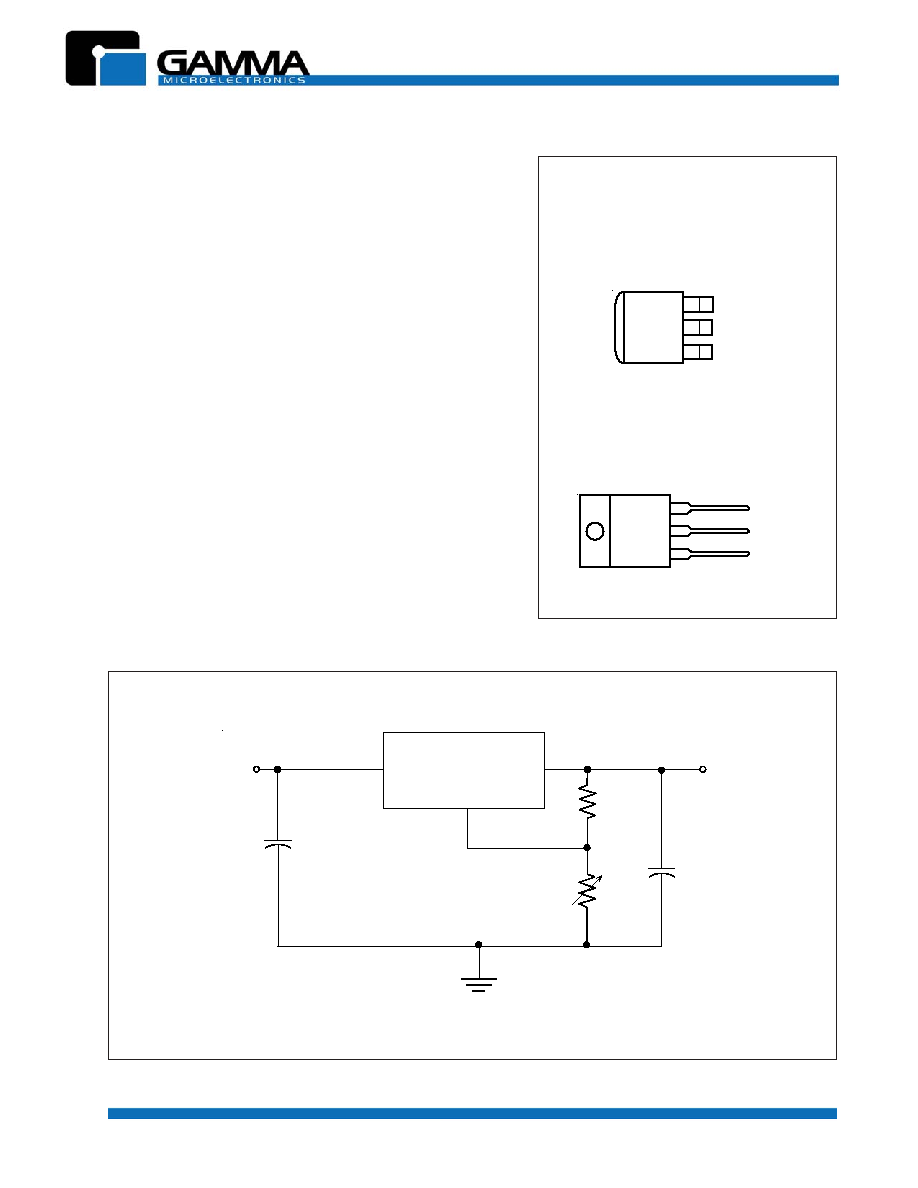
3
2
1
INPUT
ADJ
OUTPUT
TO-220 3-LEAD
3
2
1
INPUT
ADJ
OUTPUT
TO-263 (D2PAK)
(Top View)
(Top View)
CONNECTION DIAGRAMS
GM317
V
OUT
V
IN
C2**
1
�
F
C1*
0.1
�
F
ADJ
OUT
IN
R1
240
R2
3
2
1
TYPICAL APPLICATION
* Use of the input bypass capacitor is recommended if the regulator is far from filter capacitors.
** Use of the output capacitor is optional. It improves transient response.
Revision 1, May 2002 www.gammamicro.com
3-TERMINAL ADJUSTABLE REGULATOR
GM317
PRELIMINARY
2
R
E
T
E
M
A
R
A
P
L
O
B
M
Y
S
N
I
M
X
A
M
T
I
N
U
t
n
e
r
r
u
C
t
u
p
u
O
I
O
0
1
0
0
5
1
A
m
e
r
u
t
a
r
e
p
m
e
T
n
o
it
c
n
u
J
l
a
u
t
r
i
V
g
n
it
a
r
e
p
O
T
J
0
5
2
1
C
�
RECOMMENDED OPERATING CONDITIONS
R
E
T
E
M
A
R
A
P
*
S
N
O
I
T
I
D
N
O
C
T
S
E
T
N
I
M
P
Y
T
X
A
M
T
I
N
U
n
o
it
a
l
u
g
e
R
t
u
p
n
I
)
2
e
t
o
N
(
V
I
V
-
O
V
0
4
o
t
V
3
=
)
3
e
t
o
N
(
T
J
= N
I
M
o
t
X
A
M
1
0
.
0
4
0
.
0
V
/
%
I
O
A
5
.
1
o
t
A
m
0
1
=
2
0
.
0
7
0
.
0
n
o
it
c
e
j
e
R
e
l
p
p
i
R
V
O
z
H
0
2
1
=
f
,
V
0
1
=
5
6
B
d
V
O
,
z
H
0
2
1
=
f
,
V
0
1
=
0
1
�
d
n
u
o
r
g
d
n
a
J
D
A
n
e
e
w
t
e
b
r
o
ti
c
a
p
a
c
F
6
6
0
8
n
o
it
a
l
u
g
e
R
t
u
p
t
u
O
I
O
A
5
.
1
o
t
A
m
0
1
=
T
J
)
3
e
t
o
N
(
C
�
5
2
=
V
O
V
5
5
5
2
V
m
V
O
>
V
5
1
.
0
5
.
0
%
I
O
A
5
.
1
o
t
A
m
0
1
=
)
3
e
t
o
N
(
V
O
V
5
0
2
0
7
V
m
V
O
>
V
5
3
.
0
5
.
1
%
e
r
u
t
a
r
e
p
m
e
T
h
ti
w
e
g
n
a
h
C
e
g
a
tl
o
V
t
u
p
t
u
O
T
J
= N
I
M
o
t
X
A
M
1
%
)
4
e
t
o
N
(
tf
ir
D
m
r
e
T
-
g
n
o
L
e
g
a
tl
o
V
t
u
p
u
O
T
t
a
h
0
0
0
1
r
e
tf
A
J
=
X
A
M
d
n
a
V
I
V
-
O
V
0
4
=
3
.
0
1
%
e
g
a
tl
o
V
e
s
i
o
N
t
u
p
t
u
O
,
z
H
k
0
0
1
o
t
z
H
0
1
=
f
T
J
=
C
�
5
2
3
0
0
.
0
%
n
i
a
t
n
a
m
o
t
t
n
e
r
r
u
C
t
u
p
t
u
O
m
u
m
i
n
i
M
n
o
it
a
l
u
g
e
R
V
I
V
-
O
V
0
4
=
5
.
3
0
1
A
m
t
n
e
r
r
u
C
l
a
n
i
m
r
e
T
-
t
n
e
m
t
s
u
j
d
A
0
5
0
0
1
�
A
e
g
n
a
h
c
t
n
e
r
r
u
C
l
a
n
i
m
r
e
T
-
t
n
e
m
t
s
u
j
d
A
V
I
V
-
O
I
,
V
0
4
o
t
V
5
.
2
=
O
A
5
.
1
o
t
A
m
0
1
=
2
.
0
5
�
A
)
J
D
A
o
t
t
u
p
t
u
o
(
e
g
a
tl
o
V
e
c
n
e
r
e
f
e
R
V
I
V
-
O
I
,
V
0
4
o
t
V
3
=
O
,
A
5
.
1
o
t
A
m
0
1
=
P
W
5
1
2
.
1
5
2
.
1
3
.
1
V
t
n
e
r
r
u
C
t
u
p
t
u
O
k
a
e
P
V
I
- V
O
V
5
1
5
.
1
2
.
2
A
V
I
- V
O
,
V
5
1
T
J
C
�
5
2
=
5
1
.
0
4
.
0
ELECTRICAL CHARACTERISTICS
over recommended ranges of operating virtual junction temperature, unless otherwise noted. (Note 1)
* Unless otherwise noted, these specifications apply for the following test conditions: V
I
- V
O
= 5V and I
O
= 0.5A.
For conditions shown as MIN or MAX, use the appropriate value specified under recommended operating conditions.
(Note 1) All characteristics are measured with a 0.1
�
F capacitor across the input and a 1
�
F capacitor across the output.
(Note 2) Input regulation is expressed here as the percentage change in output voltage per 1V change at the input.
(Note 3) Pulse testing techniques are used to mantain the junction temperature as close to the ambient temperature as possible.
Thermal effects must be taken into account separately.
(Note 4) Since long-term drift cannot be measured on the individual devices prior to shipment, this specification is not intended to be
a guarantee or warranty. It is an engineering estimate of the average drift to be expected from lot to lot.
Revision 1, May 2002 www.gammamicro.com
3-TERMINAL ADJUSTABLE REGULATOR
GM317
PRELIMINARY
3
G
N
I
T
A
R
E
U
L
A
V
T
I
N
U
V
,
e
g
a
tl
o
V
l
a
it
n
e
r
e
ff
i
D
t
u
p
t
u
O
o
t
t
u
p
n
I
I
V
-
O
0
4
V
5
2
t
a
n
o
it
a
p
i
s
s
i
D
l
a
t
o
T
s
u
o
u
n
it
n
o
C
e
r
u
t
a
r
e
p
m
e
t
r
i
a
-
e
e
r
f
C
�
2
W
5
2
)
w
o
ll
e
b
r
o
(
t
a
n
o
it
a
p
i
s
s
i
D
l
a
t
o
T
s
u
o
u
n
it
n
o
C
e
r
u
t
a
r
e
p
m
e
t
e
s
a
c
C
�
5
1
e
g
n
a
R
e
r
u
t
a
r
e
p
m
e
T
s
n
o
it
c
n
u
j
l
a
u
t
r
i
v
r
o
,
e
s
a
c
,r
i
a
-
e
e
r
f
g
n
it
a
r
e
p
O
5
2
1
+
o
t
0
C
�
e
g
n
a
R
e
r
u
t
a
r
e
p
m
e
T
e
g
a
r
o
t
S
0
5
1
+
o
t
5
6
-
(
m
m
6
.
1
e
r
u
t
a
r
e
p
m
e
T
d
a
e
L
6
1
/
1
s
d
n
o
c
e
s
0
1
r
o
f
e
s
a
c
m
o
r
f
)
h
c
n
i
0
6
2
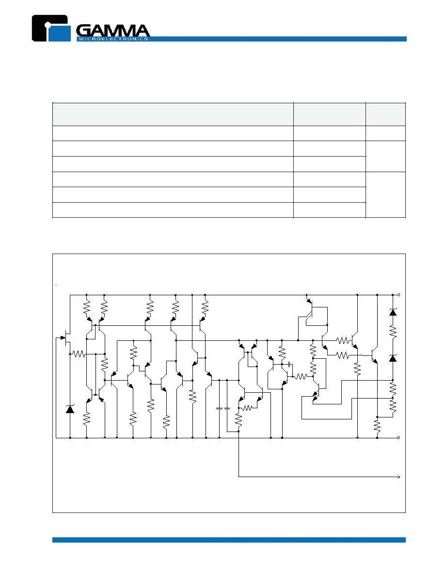
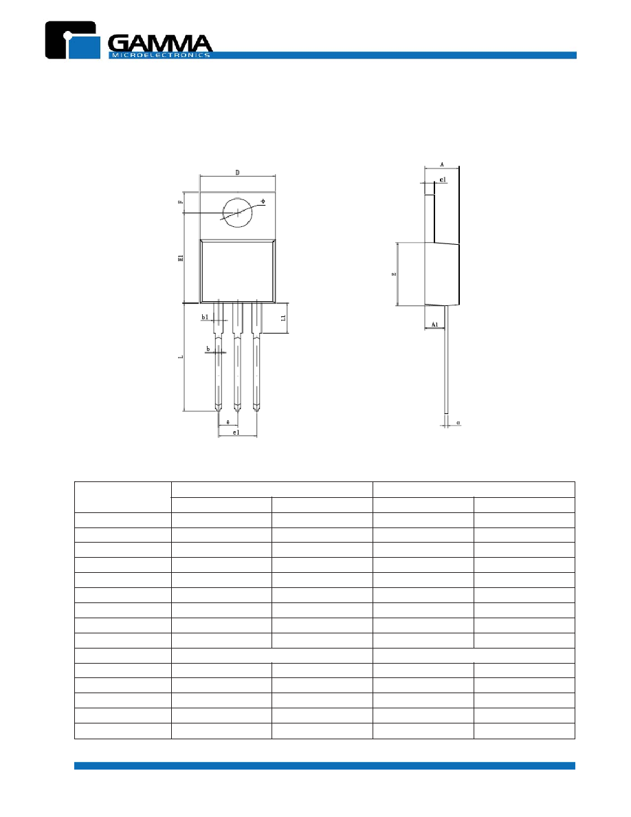
ABSOLUTE MAXIMUM RATINGS
SCHEMATIC DIAGRAM
V
I N
V
O U T
ADJ
6.3V
13k
6.3V
105
4.0
0.1
200
160
170
510
12k
6.8k
5pF
6.7k
2.4k
12.5k
30pF
30pF
5.1k
110
5.8k
3.6k
6.3V
190
125k
31
310
230
120
5.6k
12.4k
135
This device contains 29 active transistors.
Revision 1, May 2002 www.gammamicro.com
3-TERMINAL ADJUSTABLE REGULATOR
GM317
PRELIMINARY
4
7
1
3
M
G
E
G
A
K
C
A
P
3
-
3
6
2
-
O
T
3
-
0
2
2
-
O
T
3
A
T
-
7
1
3
M
G
3
B
T
-
7
1
3
M
G
ORDERING INFORMATION
Revision 1, May 2002 www.gammamicro.com
3-TERMINAL ADJUSTABLE REGULATOR
GM317
PRELIMINARY
5
L
O
B
M
Y
S
s
r
e
t
e
m
il
li
M
n
I
s
n
o
i
s
n
e
m
i
D
s
e
h
c
n
I
n
I
s
n
o
i
s
n
e
m
i
D
N
I
M
X
A
M
N
I
M
X
A
M
A
0
7
4
.
4
0
7
6
.
4
6
7
1
.
0
4
8
1
.
0
1
A
0
2
5
.
2
0
2
8
.
2
9
9
0
.
0
1
1
1
.
0
b
0
1
7
.
0
0
1
9
.
0
8
2
0
.
0
6
3
0
.
0
1
b
0
7
1
.
1
0
7
3
.
1
6
4
0
.
0
4
5
0
.
0
c
0
1
3
.
0
0
3
5
.
0
2
1
0
.
0
1
2
0
.
0
1
c
0
7
1
.
1
0
7
3
.
1
6
4
0
.
0
4
5
0
.
0
D
0
1
0
.
0
1
0
1
3
.
0
1
4
9
3
.
0
6
0
4
.
0
E
0
0
5
.
8
0
0
9
.
8
5
3
3
.
0
0
5
3
.
0
1
E
0
6
0
.
2
1
0
6
4
.
2
1
5
7
4
.
0
1
9
4
.
0
e
P
Y
T
0
4
5
.
2
P
Y
T
0
0
1
.
0
1
e
0
8
9
.
4
0
8
1
.
5
6
9
1
.
0
4
0
2
.
0
F
0
9
5
.
2
0
9
8
.
2
2
0
1
.
0
4
1
1
.
0
L
0
0
4
.
3
1
0
0
8
.
3
1
8
2
5
.
0
3
4
5
.
0
1
L
0
6
5
.
3
0
6
9
.
3
0
4
1
.
0
6
5
1
.
0
0
9
7
.
3
0
9
8
.
3
9
4
1
.
0
3
5
1
.
0
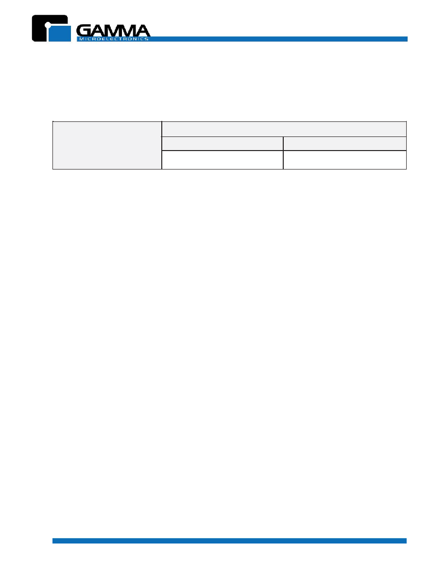
TO-220-3L PACKAGE OUTLINE DIMENSIONS