GM431
ADJUSTABLE SHUNT REGULATOR
Revision 2, February 2003 1 www.gammamicro.com
PRELIMINARY
+
_
Wide operating current range, 1 mA to 100mA
Low dynamic output impedance, 0.2
typ.
0.5%, 1% or 2% reference voltage tolerance
Alternate for TL1431, TL431, LM431 & AS431
Industrial temperature range -40∞ to +85∞ C
Available in SOT-23-3, TO-92, SOT-89 and SOP-8 packages
2
3
1
3
2
3
1
2
1
2
3
4
8
7
6
5
CATHODE
CATHODE
CATHODE
ANODE
ANODE
ANODE
ANODE
ANODE
REF
REF
NC
REF
NC
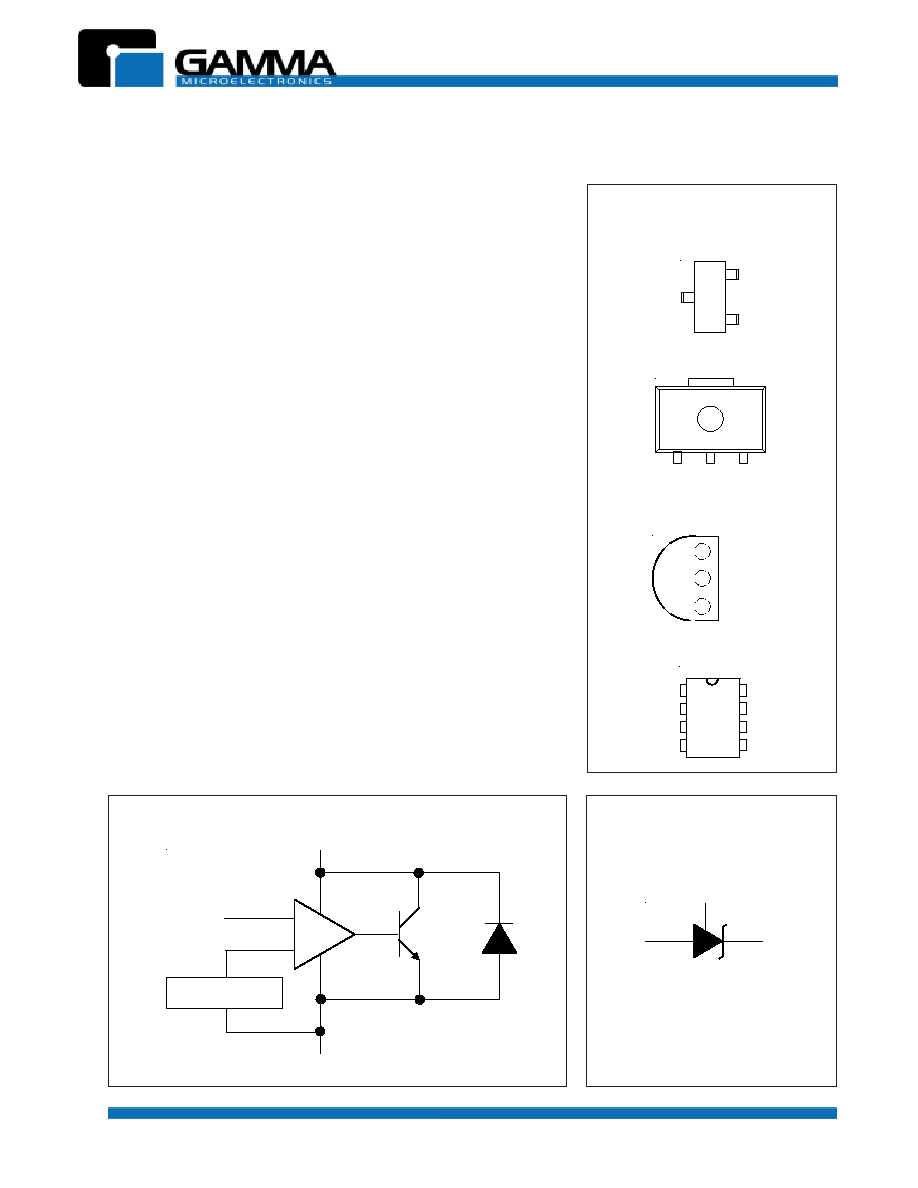
SOT-23-3 (TOP VIEW)
TO-92 (TOP VIEW)
SOP-8 (TOP VIEW)
PIN CONFIGURATIONS
ANODE
Switching power supplies
Linear regulators
Adjustable supplies
Battery-operated computers
Computer disk drives
Instrumentation
Applications:
V
ref
CATHODE
ANODE
REFERENCE
REFERENCE
ANODE
CATHODE
BLOCK DIAGRAM (POSITIVE LOGIC)
LOGIC SYMBOL
The GM431 is a three terminal adjustable shunt regulator with ther-
mal stability guaranteed over temperature. Output voltage can be
adjusted to any value from 2.5V
(V
ref
) to 36V using two external
resistors. The GM431 has a typical dynamic output impedance of
0.2
. Active output circuitry provides a very sharp turn on character-
istic, making the GM431 an excellent replacement for zener diodes
in many applications such as onboard regulation and adjustable
power supplies. The GM431 is an ideal voltage reference for 3.0 to
3.3V switching power supplies.
The GM431 shunt regulator is available with 3 voltage tolerances
0.5%, 1.0% and 2.0% over T
A
= -40∞C to +85∞C , and four package
options (SOT-23-3, TO-92, SOT-89 and SOP-8). Whatever your ap-
plication, the GM431 offers the optimum combination of performance,
reliability and economy.
1
3
2
SOT-89 (TOP VIEW)
CATHODE
ANODE
REF
GM431
ADJUSTABLE SHUNT REGULATOR
Revision 2, February 2003 2 www.gammamicro.com
PRELIMINARY
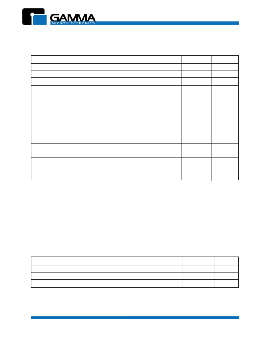
PARAMETER
SYMBOL
MAXIMUM
UNIT
Cathode Voltage
(1)
V
KA
37
V
Continuous cathode current
I
K
150
mA
Reference input current
I
ref
10
mA
Power dissipation at TA = 25∫ C
SOT-23
P
D
0.37
W
SO-8
0.78
TO-92
0.95
Package thermal impedance
(2, 3)
SOT-23-3
JA
336
∫C/W
TO-92
132
SO-8
163
Operating ambient temperature range
T
A
-40 to +85
∫C
Operating junction temperature range
T
J
-40 to +150
∫C
Lead temperature (soldering) 10 seconds
T
LEAD
300
∫C
Storage temperature range
T
STG
-65 to + 150
∫C
ESD rating (human body model)
V
ESD
2
kV
ABSOLUTE MAXIMUM RATINGS
(over free-air temperature range except as noted)
These are stress ratings only. Functional operation of the device at these or any conditions beyond the
"recommended operatiing conditions" is not implied. Exposure to absolute maximum rated conditions may affect
device reliability.
NOTES:
1. Voltage values are with respect to the anode except as noted.
2. Maximum power dissipation is a function of T
J(max)
,
JA
and T
A
. Maximum allowable power dissipation at any allowable ambient
temperature is P
D
= (T
J(max)
- T
A
)/
JA
. Operation at absolute maximum T
J
of 150∫ C can affect device reliability.
3. Package thermal impedance is calculated per JESD 51.
PARAMETER
SYMBOL MINIMUM MAXIMUM
UNIT
Cathode Voltage
V
KA
V
ref
36
V
Cathode Current
I
K
1.0
100
mA
Operating free-air temperature range
T
A
-40
+85
∫C
RECOMMENDED OPERATING CONDITIONS
GM431
ADJUSTABLE SHUNT REGULATOR
Revision 2, February 2003 3 www.gammamicro.com
PRELIMINARY
PARAMETER
CONDITION
MIN
TYP
MAX
UNIT
Reference Voltage
V
ref
V
KA
= V
ref
, I
K
= 10 mA, T
A
= 25∫ C
(1)
2.475
2.500
2.525
V
V
KA
= V
ref
, I
K
= 10 mA, T
A
= -40 to +85∫ C
(1)
V
ref
temp deviation
V
dev
V
KA
= V
ref
, IK = 10 mA
(1)
8
25
mV
Ratio of change in V
ref
V
ref
to change in V
KA
V
KA
I
K
= 10mA,
V
KA
= 16V to V
ref
-0.5
-2.7 mV/V
Reference input current
I
ref
I
K
= 10mA, R1 = 10K
, R2 =
(2)
0.5
4.0
µ
A
I
ref
temp deviation
I
ref(dev)
I
K
= 10mA, R1 = 10K
, R2 =
(2)
0.4
1.2
µ
A
T
A
= full range
Minimum operating
I
K(min)
V
KA
= V
ref
(1)
100
µ
A
current
Off-state cathode current
I
K(off)
V
KA
= 36V, V
ref
= 0V
(3)
0.04
0.50
µ
A
V
KA
= 16V, V
ref
= 0V
(3)
Dynamic impedance
| Z
KA
|
f
1kHz, V
KA
= V
ref
, IK = 100
µ
A to 100mA
(1)
0.25
0.50
ELECTRICAL CHARACTERISTICS
(T
A
= 25∫ C unless otherwise noted)
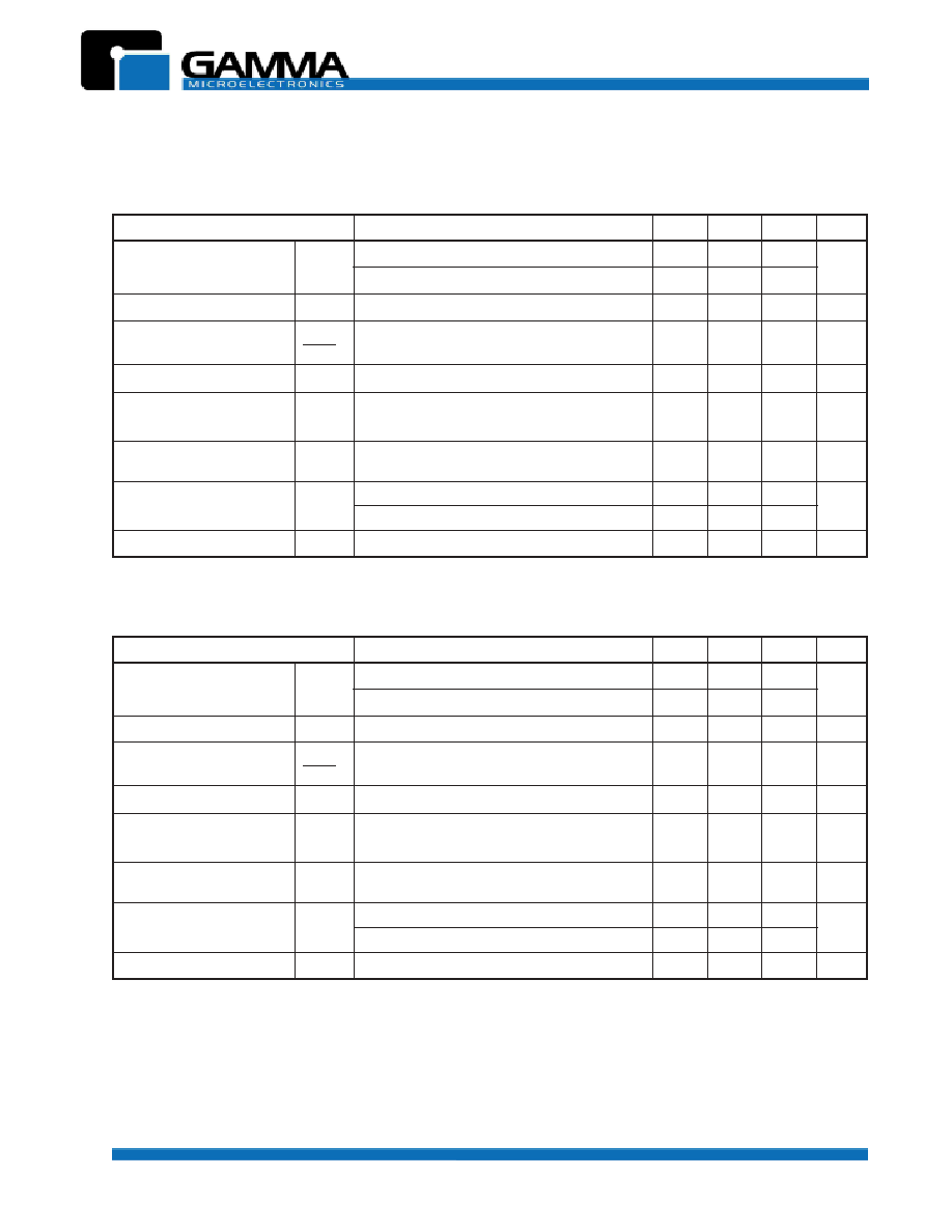
GM431B (1.0%)
PARAMETER
CONDITION
MIN
TYP
MAX
UNIT
Reference Voltage
V
ref
V
KA
= V
ref
, I
K
= 10 mA, T
A
= 25∫ C
(1)
2.487
2.500
2.512
V
V
KA
= V
ref
, I
K
= 10 mA, T
A
= -40 to +85∫ C
(1)
V
ref
temp deviation
V
dev
V
KA
= V
ref
, IK = 10 mA
(1)
8
17
mV
Ratio of change in V
ref
V
ref
to change in V
KA
V
KA
I
K
= 10mA,
V
KA
= 16V to V
ref
-0.5
-2.7 mV/V
Reference input current
I
ref
I
K
= 10mA, R1 = 10K
, R2 =
(2)
0.5
4.0
µ
A
I
ref
temp deviation
I
ref(dev)
I
K
= 10mA, R1 = 10K
, R2 =
(2)
0.4
12
µ
A
T
A
= full range
Minimum operating
I
K(min)
V
KA
= V
ref
(1)
100
µ
A
current
Off-state cathode current
I
K(off)
V
KA
= 36V, V
ref
= 0V
(3)
0.04
0.50
µ
A
V
KA
= 16V, V
ref
= 0V
(3)
Dynamic impedance
| Z
KA
|
f
1kHz, V
KA
= V
ref
, IK = 100
µ
A to 100mA
(1)
0.25
0.50
GM431A (0.5%)
NOTES:
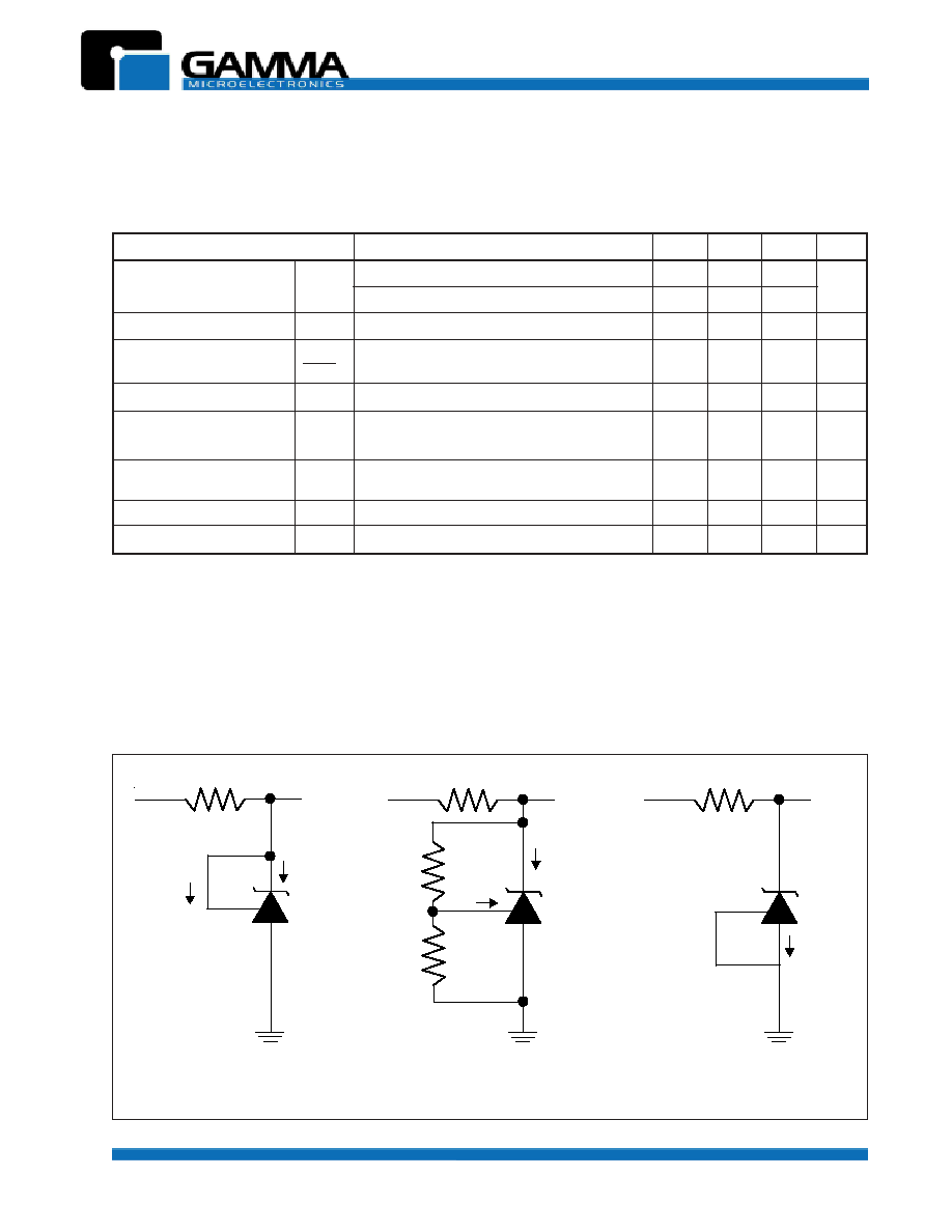
(1) See test circuit 1 on page 4.
(2) See test circuit 2 on page 4.
(3) See test circuit 3 on page 4.
GM431
ADJUSTABLE SHUNT REGULATOR
Revision 2, February 2003 4 www.gammamicro.com
PRELIMINARY
V
IN
V
KA
I
K
I
ref
V
ref
I
K
(off)
R1
R2
V
IN
V
IN
V
KA
V
KA
I
ref
I
K
Test Circuit 1
V
KA
= V
ref
Test Circuit 3
Off-State
Test Circuit 2
V
KA
> V
ref
TEST CIRCUITS
PARAMETER
CONDITION
MIN
TYP
MAX
UNIT
Reference Voltage
V
ref
V
KA
= V
ref
, I
K
= 10 mA, T
A
= 25∫ C
(1)
2.45
2.5
2.55
V
V
KA
= V
ref
, I
K
= 10 mA, T
A
= -40 to +85∫ C
(1)
V
ref
temp deviation
V
dev
V
KA
= V
ref
, IK = 10 mA
(1)
15
30
mV
Ratio of change in V
ref
V
ref
to change in V
KA
V
KA
I
K
= 10mA,
V
KA
= 10V to V
ref
-0.5
-2.7 mV/V
Reference input current
I
ref
I
K
= 10mA, R1 = 10K
, R2 =
(2)
0.5
4
µ
A
I
ref
temp deviation
I
ref(dev)
I
K
= 10mA, R1 = 10K
, R2 =
(2)
0.4
1.2
µ
A
T
A
= full range
Minimum operating
I
K(min)
V
KA
= V
ref
(1)
100
µ
A
current
Off-state cathode current
I
K(off)
V
KA
= 36V, V
ref
= 0V
(3)
0.04
0.50
µ
A
Dynamic impedance
| Z
KA
|
f
1kHz, V
KA
= V
ref
, IK = 100
µ
A to 100mA
(1)
0.25
0.50
GM431C (2.0%)
NOTES:
(1) See test circuit 1.
(2) See test circuit 2.
(3) See test circuit 3.
ELECTRICAL CHARACTERISTICS
(T
A
= 25∫ C unless otherwise noted)

GM431
ADJUSTABLE SHUNT REGULATOR
Revision 2, February 2003 5 www.gammamicro.com
PRELIMINARY
IK vs VKA
-400
-200
0
200
400
600
800
1000
-1
-0.5
0
0.5
1
1.5
2
2.5
3
VKA(V)
IK
(
u
A
)
-150
-100
-50
0
50
100
150
-2
-1
0
1
2
3
Vref
IK