GM432
1.24V ADJUSTABLE PRECISION SHUNT REGULATORS
Revision 1, May 2002 www.gammamicro.com
+
_
Low-voltage operation, down to 1.24V
0.5%, 1% or 2% reference voltage tolerance
Adjustable output voltage, V
O
= V
ref
to 16V
Wide operating current range, 80
µµ
µµ
µ
A to 100mA
Low dynamic output impedance, 0.05
typical
Wide temperature range, -40∫ to +85∫ C
Pin-to-pin replacement for TLV431, SC431L
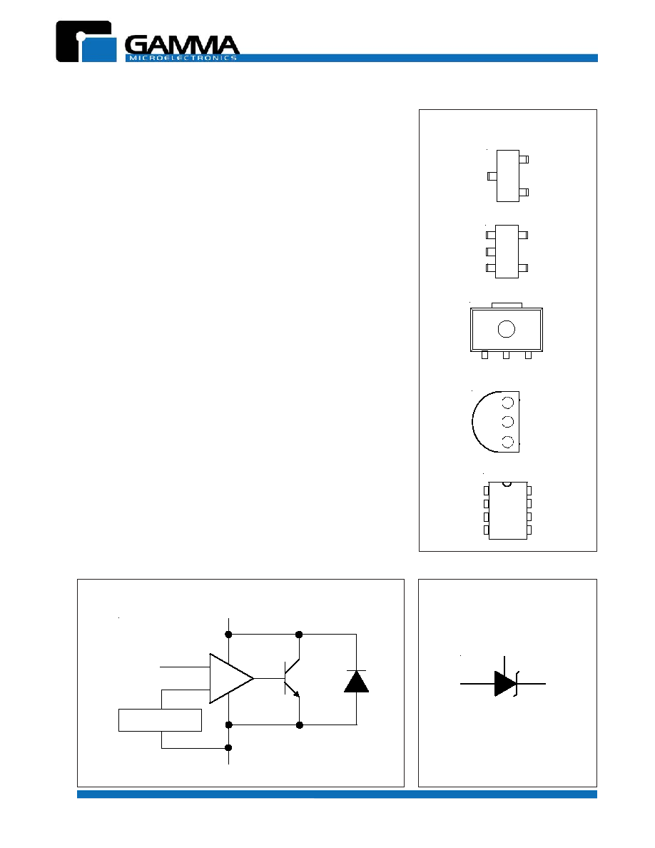
Available in SOT-23-3, SOT-23-5, SOT-89 TO-92 and SO-8
The GM432's are low-voltage three-terminal adjustable precision shunt
regulators with specified thermal stability over their full temperature
range. Output voltage can be set to any value from V
ref
(1.24V) to
16V using two external resistors. Their active output circuitry pro-
vides a very sharp turn-on characteristIc, making them excellent re-
placements for zener diodes in many applications such as onboard
regulation and adjustable power supplies. At home in a wide range of
applications, these versatile darlings are ideal voltage references for
3.0V to 3.3V switching power suppies. With operational cathode
current as low as 80
µ
A, batteries keep on going. Whatever your
application, the GM432's offer the optimum combination of perfor-
mance, reliability, and economy.
2
3
1
3
2
3
1
2
1
2
3
4
8
7
6
5
CATHODE
CATHODE
CATHODE
ANODE
ANODE
ANODE
ANODE
ANODE
REF
REF
NC
REF
NC
SOT-23-3 (TOP VIEW)
TO-92 (TOP VIEW)
SO-8 (TOP VIEW)
PIN CONFIGURATIONS
ANODE
3
1
2
4
5
SOT-23-5 (TOP VIEW)
REF
ANODE
CATHODE
NC
NC
Switching power supplies
Linear regulators
Adjustable power supplies
Battery-operated computers, PDA's, portable devices
Monitors, TV's, VCR's, camcorders
Computer disk drives
Instrumentation
Applications include:
V
ref
= 1.24V
CATHODE
ANODE
REFERENCE
REFERENCE
ANODE
CATHODE
BLOCK DIAGRAM (POSITIVE LOGIC)
LOGIC SYMBOL
1
1
3
2
SOT-89 (TOP VIEW)
CATHODE
ANODE
REF
GM432
1.24V ADJUSTABLE PRECISION SHUNT REGULATORS
Revision 1, May 2002 www.gammamicro.com
2
PARAMETER
SYMBOL
MAXIMUM
UNIT
Cathode Voltage
(1)
V
KA
20
V
Continuous cathode current
I
K
100
mA
Reference input current
I
ref
3
mA
Power dissipation at TA = 25∫ C
SOT-23
P
D
0.37
W
SO-8
0.49
TO-92
0.95
Package thermal impedance
(2, 3)
SOT-23-3
JA
336
∫C/W
SOT-23-5
256
TO-92
132
SO-8
97
Operating ambient temperature range
T
A
-40 to +85
∫C
Operating junction temperature range
T
J
-40 to +150
∫C
Lead temperature (soldering) 10 seconds
T
LEAD
300
∫C
Storage temperature range
T
STG
-65 to + 150
∫C
ESD rating (human body model)
V
ESD
2
kV
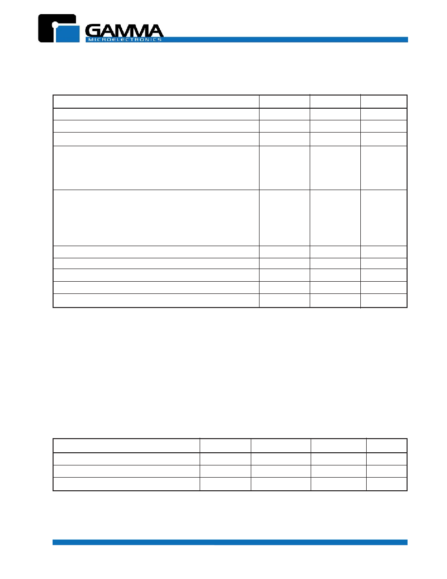
ABSOLUTE MAXIMUM RATINGS
(over free-air temperature range except as noted)
These are stress ratings only. Functional operation of the device at these or any conditions beyond the
"recommended operatiing conditions" is not implied. Exposure to absolute maximum rated conditions may affect
device reliability.
NOTES:
1. Voltage values are with respect to the anode except as noted.
2. Maximum power dissipation is a function of T
J(max)
,
JA
and T
A
. Maximum allowable power dissipation at any allowable ambient
temperature is P
D
= (T
J(max)
- T
A
)/
JA
. Operation at absolute maximum T
J
of 150∫ C can affect device reliability.
3. Package thermal impedance is calculated per JESD 51.
PARAMETER
SYMBOL MINIMUM MAXIMUM
UNIT
Cathode Voltage
V
KA
V
ref
16
V
Cathode Current
I
K
80
µ
A
100mA
Operating free-air temperature range
T
A
-40
+85
∫C
RECOMMENDED OPERATING CONDITIONS
GM432
1.24V ADJUSTABLE PRECISION SHUNT REGULATORS
Revision 1, May 2002 www.gammamicro.com
PARAMETER
CONDITION
MIN
TYP
MAX
UNIT
Reference Voltage
V
ref
V
KA
= V
ref
, I
K
= 10 mA, T
A
= 25∫ C
(1)
1.234
1.240
1.246
V
V
KA
= V
ref
, I
K
= 10 mA, T
A
= -40 to +85∫ C
(1)
1.222
1.258
V
ref
temp deviation
V
dev
V
KA
= V
ref
, IK = 10 mA
(1)
10
25
mV
Ratio of change in V
ref
V
ref
to change in V
KA
V
KA
I
K
= 10mA,
V
KA
= 16V to V
ref
1.0
2.7 mV/V
Reference input current
I
ref
I
K
= 10mA, R1 = 10K
, R2 =
(2)
0.15
0.5
µ
A
I
ref
temp deviation
I
ref(dev)
I
K
= 10mA, R1 = 10K
, R2 =
(2)
0.1
0.4
µ
A
T
A
= full range
Minimum operating
I
K(min)
V
KA
= V
ref
(1)
20
80
µ
A
current
Off-state cathode current
I
K(off)
V
KA
= 6V, V
ref
= 0V
(3)
0.125
0.150
µ
A
V
KA
= 16V, V
ref
= 0V
(3)
0.135
0.150
Dynamic impedance
| Z
KA
|
f
1kHz, V
KA
= V
ref
, IK = 100
µ
A to 100mA
(1)
0.05
0.15
3
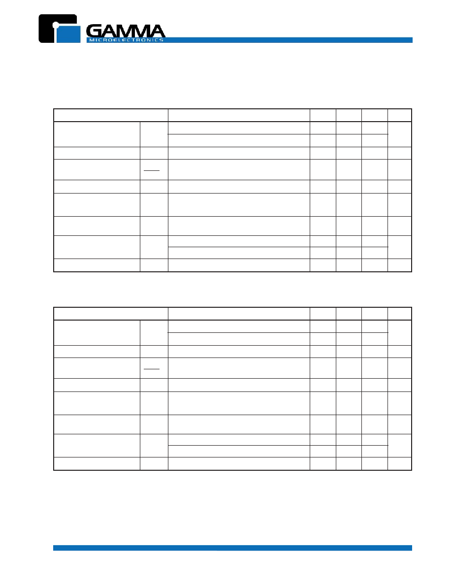
ELECTRICAL CHARACTERISTICS
(T
A
= 25∫ C unless otherwise noted)
GM432 (0.5%)
PARAMETER
CONDITION
MIN
TYP
MAX
UNIT
Reference Voltage
V
ref
V
KA
= V
ref
, I
K
= 10 mA, T
A
= 25∫ C
(1)
1.228
1.240
1.252
V
V
KA
= V
ref
, I
K
= 10 mA, T
A
= -40 to +85∫ C
(1)
1.215
1.258
V
ref
temp deviation
V
dev
V
KA
= V
ref
, IK = 10 mA
(1)
10
25
mV
Ratio of change in V
ref
V
ref
to change in V
KA
V
KA
I
K
= 10mA,
V
KA
= 16V to V
ref
1.0
2.7 mV/V
Reference input current
I
ref
I
K
= 10mA, R1 = 10K
, R2 =
(2)
0.15
0.5
µ
A
I
ref
temp deviation
I
ref(dev)
I
K
= 10mA, R1 = 10K
, R2 =
(2)
0.1
0.4
µ
A
T
A
= full range
Minimum operating
I
K(min)
V
KA
= V
ref
(1)
20
80
µ
A
current
Off-state cathode current
I
K(off)
V
KA
= 6V, V
ref
= 0V
(3)
0.125
0.150
µ
A
V
KA
= 16V, V
ref
= 0V
(3)
0.135
0.150
Dynamic impedance
| Z
KA
|
f
1kHz, V
KA
= V
ref
, IK = 100
µ
A to 100mA
(1)
0.05
0.15
GM432 (1.0%)
NOTES:
(1) See test circuit 1 on page 4.
(2) See test circuit 2 on page 4.
(3) See test circuit 3 on page 4.
GM432
1.24V ADJUSTABLE PRECISION SHUNT REGULATORS
Revision 1, May 2002 www.gammamicro.com
V
IN
V
KA
I
K
I
ref
V
ref
I
K
(off)
R1
R2
V
IN
V
IN
V
KA
V
KA
I
ref
I
K
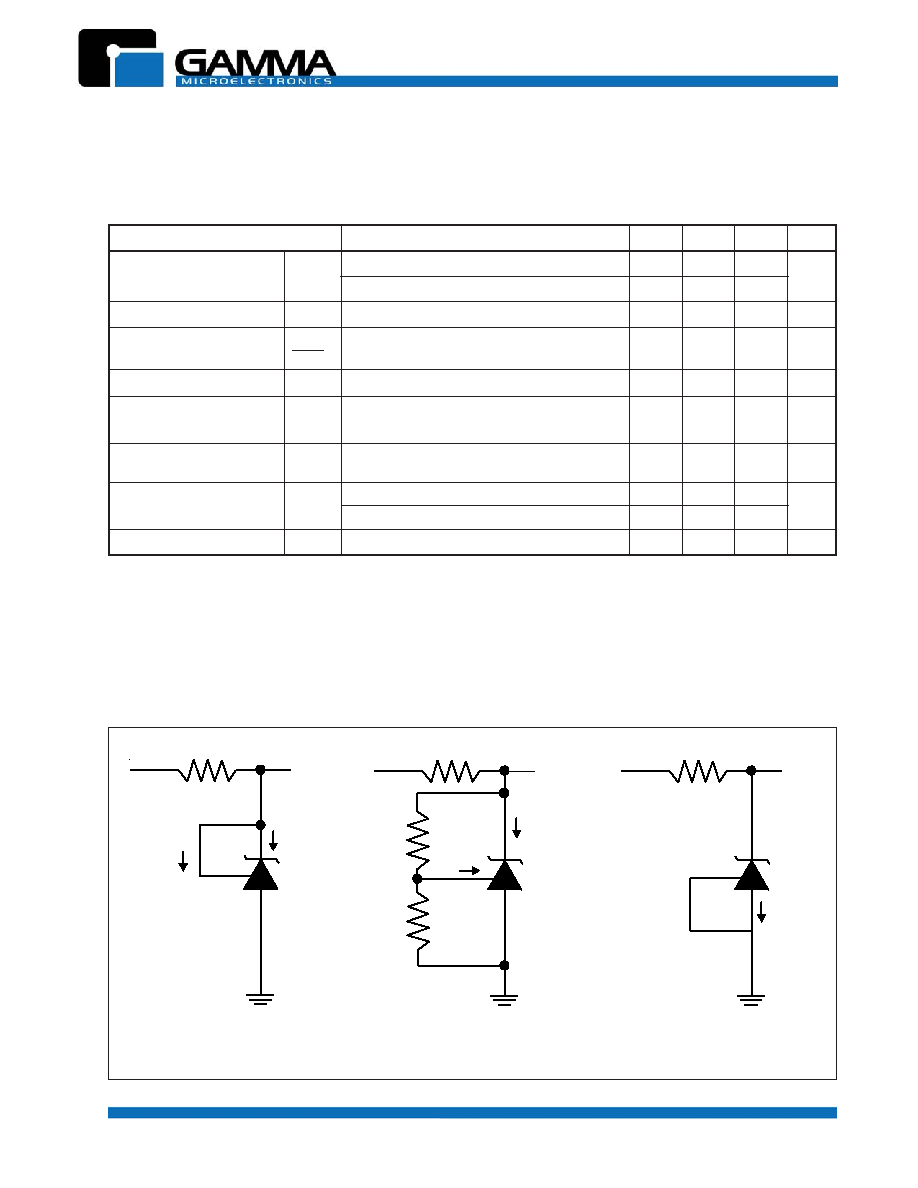
Test Circuit 1
V
KA
= V
ref
Test Circuit 3
Off-State
Test Circuit 2
V
KA
> V
ref
TEST CIRCUITS
PARAMETER
CONDITION
MIN
TYP
MAX
UNIT
Reference Voltage
V
ref
V
KA
= V
ref
, I
K
= 10 mA, T
A
= 25∫ C
(1)
1.215
1.240
1.265
V
V
KA
= V
ref
, I
K
= 10 mA, T
A
= -40 to +85∫ C
(1)
1.200
1.280
V
ref
temp deviation
V
dev
V
KA
= V
ref
, IK = 10 mA
(1)
10
35
mV
Ratio of change in V
ref
V
ref
to change in V
KA
V
KA
I
K
= 10mA,
V
KA
= 16V to V
ref
1.0
2.7 mV/V
Reference input current
I
ref
I
K
= 10mA, R1 = 10K
, R2 =
(2)
0.15
0.5
µ
A
I
ref
temp deviation
I
ref(dev)
I
K
= 10mA, R1 = 10K
, R2 =
(2)
0.1
0.4
µ
A
T
A
= full range
Minimum operating
I
K(min)
V
KA
= V
ref
(1)
20
80
µ
A
current
Off-state cathode current
I
K(off)
V
KA
= 6V, V
ref
= 0V
(3)
0.125
0.150
µ
A
V
KA
= 16V, V
ref
= 0V
(3)
0.135
0.150
Dynamic impedance
| Z
KA
|
f
1kHz, V
KA
= V
ref
, IK = 100
µ
A to 100mA
(1)
0.05
0.15
GM432 (2.0%)
NOTES:
(1) See test circuit 1.
(2) See test circuit 2.
(3) See test circuit 3.
ELECTRICAL CHARACTERISTICS
(T
A
= 25∫ C unless otherwise noted)
4
GM432
1.24V ADJUSTABLE PRECISION SHUNT REGULATORS
Revision 1, May 2002 www.gammamicro.com
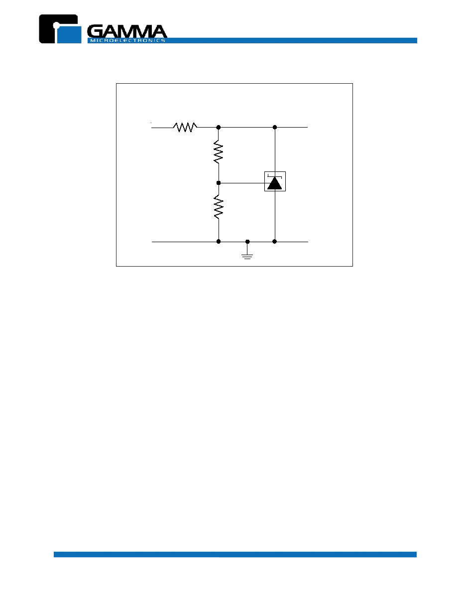
TYPICAL APPLICATION CIRCUIT
o
o
V
OUT
GND
GM432
R
R1
R2
o
o
V
IN
V
REF
Notes:
1) Set V
OUT
according to the following equation:
V
OUT
= V
REF
(
1 +
______
)
+ I
REF
R1
2) Choose the value for R as follows:
∑
The maximum limit for R should be such that the cathode current, I
K
, is
greater than the minimum operating current (80
µ
A) at V
IN(MIN)*
∑
The minimum limit for R should be such that the cathode current, I
K
,
does not exceed 100mA under all load conditions, and the instantanenous
turn-on value for I
K
does not exceed 150 mA. Both of the following condi-
tions must be met:
R
min
$
______________
(to limit instantaneous turn-on I
K
)
R
min
$
__________________
(to limit I
K
under normal operating conditions)
R1
R2
V
IN(max)
150 mA
V
IN(max)
-
V
OUT
I
OUT(min)
+
100mA
5