Revision 1, May 2002 www.gammamicro.com
7.5A PRECISION LINEAR REGULATORS
GM6608
PRELIMINARY
1
Adjustable or Fixed Output
Output Current of 7.5A
Typical Dropout Voltage 1.2V @ 7.5A
Maximum Line Regulation 0.2%
Maximum Load Regulation 0.4%
Fast Transient Response
Current Limit Protection
Thermal Shutdown Protection
The GM6608 series of positive adjustable and fixed
regulators are designed to provide 7.5A output with
low dropout voltage performance. On-chip trimming
adjusts the reference voltage to 2%. Put them to work
in post regulators or microprocessor power supplies
where low voltage operation and fast transient
response are required.
The fast loop response and low dropout voltage make
this regulator ideal for applications where low voltage
operation and good transient response are important.
The GM6608's are available in TO-220 and surface-
mount TO263 packages.
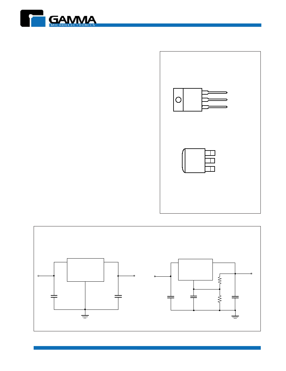
CONNECTION DIAGRAMS
Applications:
PC Motherboards
Post Regulators for Switching Supplies
Microcontroller Systems
Low power Microprocessor Systems
3
2
1
VIN
VOUT
ADJ / GND*
TO-220 3-LEAD
VIN
VOUT
ADJ/GND*
TO-263 (D2PAK)
3
2
1
* On fixed versions Pin1=GND,
on adjustable versions Pin1=ADJ
V
OUT
GND
V
IN
3.3V @ 7.5A
22
�
F
5.0V
10
�
F
5.0V
GM6608-3.3
TYPICAL APPLICATION CIRCUITS
(Fixed Version)
(
Adjustable
Version)
V
OUT
ADJ
V
IN
3.3V @ 7.5A
22
�
F
5.0V
10
�
F
5.0V
GM6608-A
5.0V
0.1
�
F
5.0V
Tant
200
1.0%
124
1.0%
(Top View)
(Top View)
Revision 1, May 2002 www.gammamicro.com
7.5A PRECISION LINEAR REGULATORS
GM6608
PRELIMINARY
3
8
0
6
6
M
G
E
G
A
K
C
A
P
e
g
a
tl
o
V
t
u
p
t
u
O
.
J
D
A
V
8
.
1
V
5
.
2
V
3
.
3
V
0
.
5
3
-
3
6
2
-
O
T
3
A
T
A
-
8
0
6
6
M
G
3
A
T
8
.
1
-
8
0
6
6
M
G
3
A
T
5
.
2
-
8
0
6
6
M
G
3
A
T
3
.
3
-
8
0
6
6
M
G
3
A
T
0
.
5
-
8
0
6
6
M
G
3
-
0
2
2
-
O
T
3
B
T
A
-
8
0
6
6
M
G
3
B
T
8
.
1
-
8
0
6
6
M
G
3
B
T
5
.
2
-
8
0
6
6
M
G
3
B
T
3
.
3
-
8
0
6
6
M
G
3
B
T
0
.
5
-
8
0
6
6
M
G
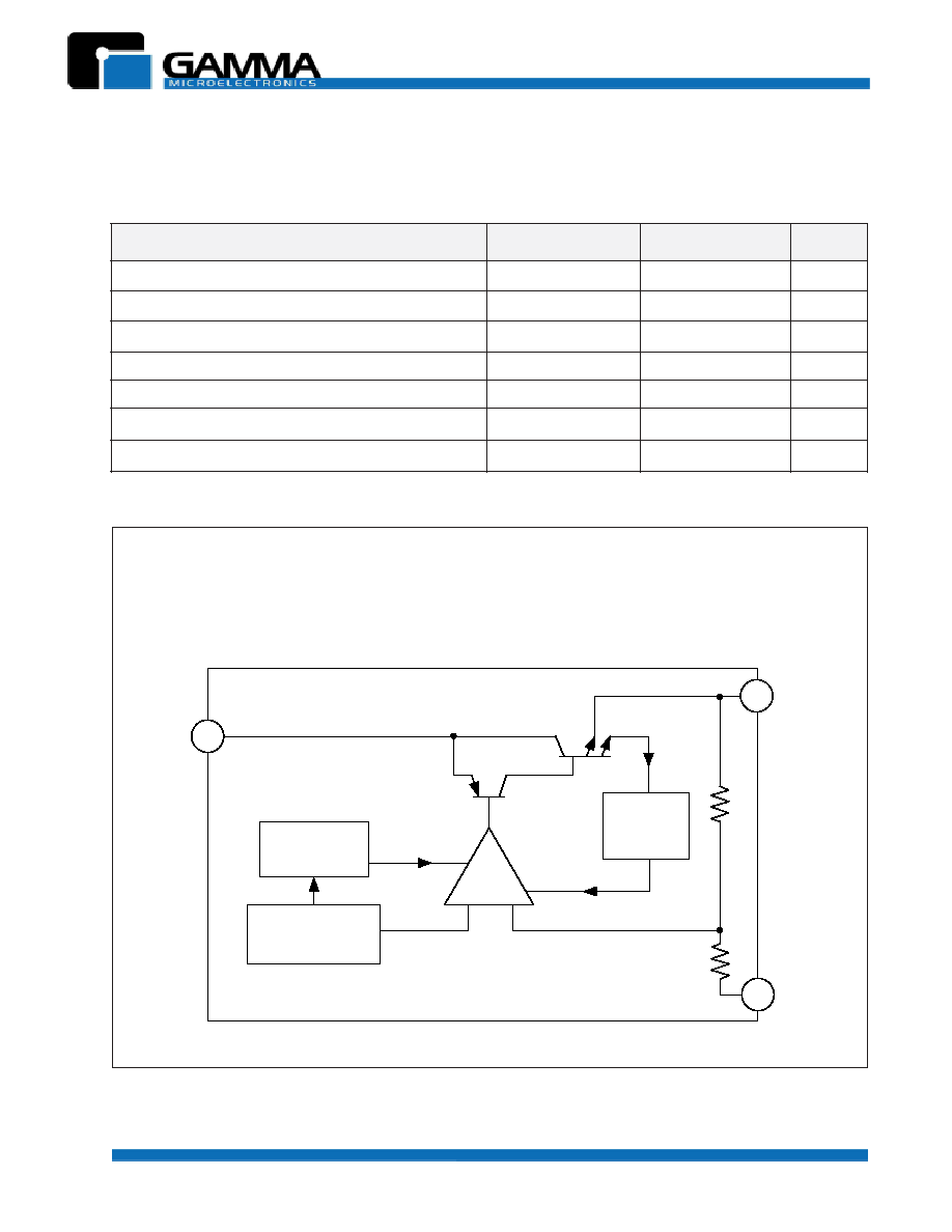
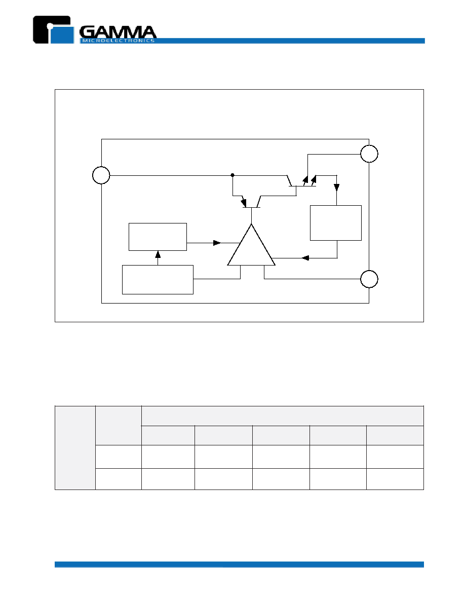
V
IN
V
OUT
ADJ
Thermal
Shutdown
Bandgap
Reference
Output
Current
Limit
Error
Amplifier
+
-
BLOCK DIAGRAM
(
Adjustable
Version)
ORDERING INFORMATION
Note: other fixed versions are available: V
OUT
= 1.5V to 5.0V
Revision 1, May 2002 www.gammamicro.com
7.5A PRECISION LINEAR REGULATORS
GM6608
PRELIMINARY
4
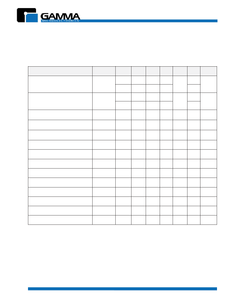
ELECTRICAL CHARACTERISTICS
Unless otherwise specified: Adjustable: V
IN
= 2.75V to 7.0V and I
O
= 10mA to 7.5A. Fixed: I
O
= 0mA to 7.5A,
V
IN
= 4.75V to 7.0V.
r
e
t
e
m
a
r
a
P
l
o
b
m
y
S
V
N
I
I
O
T
J
)
5
(
n
i
M
p
y
T
x
a
M
t
i
n
U
e
g
a
tl
o
V
t
u
p
t
u
O
)
1
(
)
s
n
o
i
s
r
e
V
d
e
x
i
F
(
V
O
V
5
A
m
0
C
�
5
2
%
1
-
V
O
%
1
+
V
.
T
.
O
%
2
-
%
2
+
e
g
a
tl
o
V
e
c
n
e
r
e
f
e
R
)
1
(
)
n
o
i
s
r
e
V
e
l
b
a
t
s
u
j
d
A
(
V
F
E
R
V
5
A
m
0
1
C
�
5
2
8
3
2
.
1
0
5
2
.
1
2
6
2
.
1
V
.
T
.
O
5
2
2
.
1
5
7
2
.
1
n
o
it
a
l
u
g
e
R
e
n
i
L
)
1
(
G
E
R
)
E
N
I
L
(
A
m
0
1
.
T
.
O
-
5
3
0
.
0
0
2
.
0
%
n
o
it
a
l
u
g
e
R
d
a
o
L
)
1
(
G
E
R
)
D
A
O
L
(
V
5
.
T
.
O
-
2
.
0
0
4
.
0
%
e
g
a
tl
o
V
t
u
o
p
o
r
D
)
2
(
)
1
(
V
D
A
5
.
7
.
T
.
O
-
2
.
1
4
.
1
V
ti
m
i
L
t
n
e
r
r
u
C
I
L
C
.
T
.
O
5
.
7
5
.
9
-
A
)
n
o
i
s
r
e
v
d
e
x
if
(
t
n
e
r
r
u
C
t
n
e
c
s
i
u
Q
I
Q
.
T
.
O
-
2
1
4
1
A
m
t
n
e
i
c
if
f
e
o
C
e
r
u
t
a
r
e
p
m
e
T
T
C
.
T
.
O
-
5
0
0
.
0
-
C
�
/
%
t
n
e
r
r
u
C
n
i
P
t
s
u
j
d
A
I
J
D
A
.
T
.
O
-
5
5
0
9
�
A
e
g
n
a
h
C
t
n
e
r
r
u
C
n
i
P
t
s
u
j
d
A
I
J
D
A
.
T
.
O
-
0
2
.
0
5
�
A
y
ti
li
b
a
t
S
e
r
u
t
a
r
e
p
m
e
T
T
S
V
5
A
5
.
0
.
T
.
O
-
0
5
.
0
-
%
t
n
e
r
r
u
C
d
a
o
L
m
u
m
i
n
i
M
)
n
o
i
s
r
e
v
.j
d
A
(
I
O
V
5
.
T
.
O
-
5
0
1
A
m
e
s
i
o
N
t
u
p
t
u
O
S
M
R
)
3
(
V
N
C
�
5
2
-
3
0
0
.
0
-
V
%
O
o
it
a
R
n
o
it
c
e
j
e
R
e
l
p
p
i
R
)
4
(
R
A
V
5
A
5
.
7
.
T
.
O
0
6
0
8
-
B
d
NOTES:
(1) Low duty cycle pulse testing with Kelvin connections required
(2)
V
OUT
,
V
REF
= 1%
(3) Bandwidth of 10 Hz to 10 kHz
(4) 120Hz input ripple (C
ADJ
for ADJ = 25
�
F)
(5) O.T. = over specified operating junction temperature range
Revision 1, May 2002 www.gammamicro.com
7.5A PRECISION LINEAR REGULATORS
GM6608
PRELIMINARY
5
The GM6608 series linear regulators provide fixed and
adjustable output voltages at currents up to 7.5 A. These
regulators are protected against overcurrent conditions
and include thermal shutdown protection. The GM6608's
have a composite PNP�NPN output transistor and
require an output capacitor for stability.
A detailed procedure for selecting this capacitor follows.
APPLICATIONS INFORMATION
Stability Considerations
The output compensation capacitor helps to determine
three main characteristics of a linear regulator's
performance: start�up delay, load transient response,
and loop stability. The capacitor value and type is based
on cost, availability, size and temperature constraints. A
tantalum or aluminum electrolytic capacitor is preferred,
as a film or ceramic capacitor with almost zero ESR
can cause instability. An aluminum electrolytic capacitor
is the least expensive type, but when the circuit operates
at low temperatures, both the value and ESR of the
capacitor will vary widely. For optimum performance over
the full operating temperature range, a tantalum
capacitor is best. A 22
�
F tantalum capacitor will work
fine in most applications, but with high current regulators
such as the GM6608 higher capacitance values will
improve the transient response and stability. Most
applications for the GM6608's involve large changes in
load current, so the output capacitor must supply
instantaneous load current. The ESR of the output
capacitor causes an immediate drop in output voltage
given by:
In microprocessor applications an output capacitor
network of several tantalum and ceramic capacitors in
parallel is commonly used. This reduces overall ESR
and minimizes the instantaneous output voltage drop
under transient load conditions. The output capacitor
network should be placed as close to the load as
possible for the best results.
V =
I x ESR
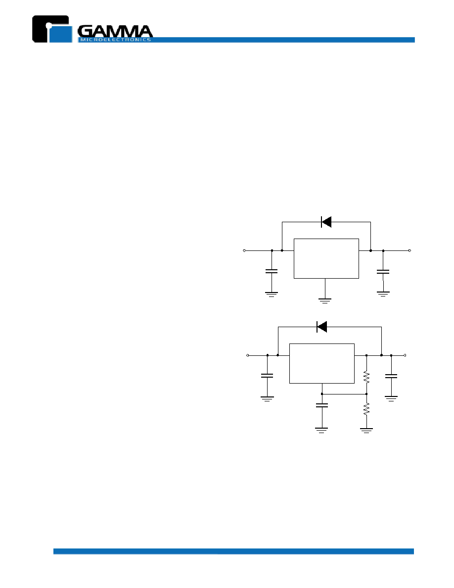
Protection Diodes
When large external capacitors are used with most linear
regulator it is wise to add protection diodes. If the input
voltage of the regulator is shorted, the output capacitor
will discharge into the output of the regulator. The
discharge current depends on the value of capacitor,
output voltage and rate at which V
IN
drops.
In the GM6608 linear regulators, the discharge path is
through a large junction, and protection diodes are
normally not needed. However, if the regulator is used
with large output capacitance values and the input
voltage is instantaneously shorted to ground, damage
can occur. In this case, a diode connected as shown
above in Figure 1.
V
OUT
GND
V
IN
GM6608-3.3
V
OUT
V
IN
C1
C2
IN4002
V
OUT
ADJ
V
IN
GM6608-A
V
OUT
V
IN
C1
C2
IN4002
R1
R2
C
ADJ
(a) Fixed Version
(b) Adjustable Version
FIGURE 1
(a),(b)
Protection Diode Scheme for
Large Output Capacitors