SYMBOL
MIN.
TYP.
MAX.
UNIT
Thermal Resistance
R
JA
≠
≠
300
(1)
∞C/W
Junction to Ambient Air
Forward Voltage
V
F
≠
≠
1.1
Volts
at I
F
= 200 mA
NOTES:
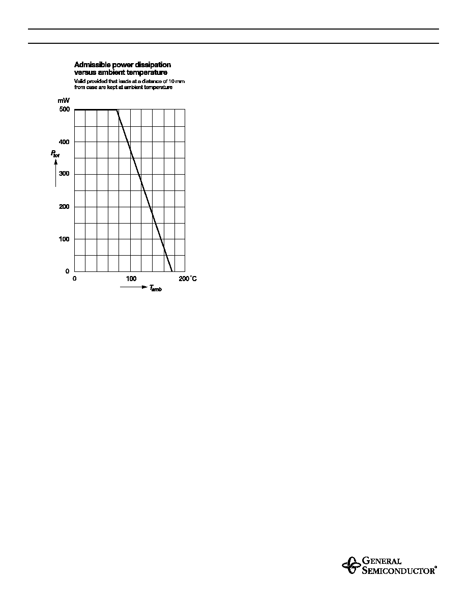
Valid provided that leads at a distance of 10 mm from case are kept at ambient temperature.
SYMBOL
VALUE
UNIT
Zener Current (see Table "Characteristics")
Power Dissipation at T
amb
= 75∞C
P
tot
500
(1)
mW
Maximum Junction Temperature
T
j
175
∞C
Storage Temperature Range
T
S
≠ 65 to +175
∞C
1/21/99
FEATURES
Silicon Planar Power Zener Diodes
Standard Zener voltage tolerance is ± 5%
with a "B" suffix. Other tolerances are
available upon request.
These diodes are also available in Mini-MELF case with
the type designation ZMM5225 ... ZMM5267, SOT-23
case with the type designation MMBZ5265 ... MMBZ5267
and SOD-23 case with the types designation MMSZ5225 ...
MMSZ5267.
MECHANICAL DATA
Case: DO-35 Glass Case
Weight: approx. 0.13 g
MAXIMUM RATINGS
Ratings at 25∞C ambient temperature unless otherwise specified.
1N5225 THRU 1N5267
ZENER DIODES
m
in.
1.
083 (27.
5)
m
in.
1.
083 (27.
5)
m
a
x
.
.
150 (3.
8)
max.
Cathode
.020 (0.52)
Mark
max.
.079 (2.0)
DO-35
Dimensions are in inches and (millimeters)
1N5225 THRU 1N5267
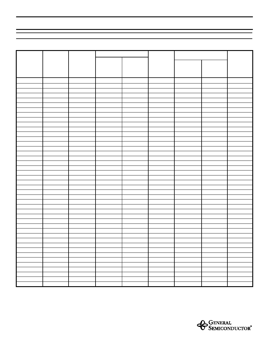
ELECTRICAL CHARACTERISTICS
Ratings at 25∞C ambient temperature unless otherwise specified.
Type
Nominal
Zener
Voltage
(3)
at
I
ZT
V
Z
(V)
Test
Current
I
ZT
(mA)
Maximum Zener impedance
(1)
Maximum
Reverse Leakage Current
at
I
ZT
Z
ZT
(
)
at
I
ZK
=0.25mA
Z
ZK
(
)
Typical
Temperature
Coefficient
VZ
(% / K)
I
R
(
µ
A)
Test Voltage
V
R
(V)
Maximum
Regulator
Current
(2)
I
ZM
(mA)
1N5225
3.0
20
29
1600
≠ 0.075
50
1.0
152
1N5226
3.3
20
28
1600
≠0.070
25
1.0
138
1N5227
3.6
20
24
1700
≠0.065
15
1.0
126
1N5228
3.9
20
23
1900
≠0.060
10
1.0
115
1N5229
4.3
20
22
2000
≠0.055
5.0
1.0
106
1N5230
4.7
20
19
1900
±0.030
5.0
2.0
97
1N5231
5.1
20
17
1600
±0.030
5.0
2.0
89
1N5232
5.6
20
11
1600
+0.038
5.0
3.0
81
1N5233
6.0
20
7
1600
+0.038
5.0
3.5
76
1N5234
6.2
20
7
1000
+0.045
5.0
4.0
73
1N5235
6.8
20
5
750
+0.050
3.0
5.0
67
1N5236
7.5
20
6
500
+0.058
3.0
6.0
61
1N5237
8.2
20
8
500
+0.062
3.0
6.5
55
1N5238
8.7
20
8
600
+0.065
3.0
6.5
52
1N5239
9.1
20
10
600
+0.068
3.0
7.0
50
1N5240
10
20
17
600
+0.075
3.0
8.0
45
1N5241
11
20
22
600
+0.076
2.0
8.4
41
1N5242
12
20
30
600
+0.077
1.0
9.1
38
1N5243
13
9.5
13
600
+0.079
0.5
9.9
35
1N5244
14
9.0
15
600
+0.082
0.1
10
32
1N5245
15
8.5
16
600
+0.082
0.1
11
30
1N5246
16
7.8
17
600
+0.083
0.1
12
28
1N5247
17
7.4
19
600
+0.084
0.1
13
27
1N5248
18
7.0
21
600
+0.085
0.1
14
25
1N5249
19
6.6
23
600
+0.086
0.1
14
24
1N5250
20
6.2
25
600
+0.086
0.1
15
23
1N5251
22
5.6
29
600
+0.087
0.1
17
21
1N5252
24
5.2
33
600
+0.087
0.1
18
19.1
1N5253
25
5.0
35
600
+0.089
0.1
19
18.2
1N5254
27
4.6
41
600
+0.090
0.1
21
16.8
1N5255
28
4.5
44
600
+0.091
0.1
21
16.2
1N5256
30
4.2
49
600
+0.091
0.1
23
15.1
1N5257
33
3.8
58
700
+0.092
0.1
25
13.8
1N5258
36
3.4
70
700
+0.093
0.1
27
12.6
1N5259
39
3.2
80
800
+0.094
0.1
30
11.6
1N5260
43
3.0
93
900
+0.095
0.1
33
10.6
1N5261
47
2.7
105
1000
+0.095
0.1
36
9.7
1N5262
51
2.5
125
1100
+0.096
0.1
39
8.9
1N5263
56
2.2
150
1300
+0.096
0.1
43
≠
1N5264
60
2.1
170
1400
+0.097
0.1
46
≠
1N5265
62
2.0
185
1400
+0.097
0.1
47
≠
1N5266
68
1.8
230
1600
+0.097
0.1
52
≠
1N5267
75
1.7
270
1700
+0.098
0.1
56
≠
NOTES:
(1) The Zener impedance is derived from the 1 kHz AC voltage which results when an AC current having an RMS value equal to 10% of the Zener current (I
ZT
or I
ZK
)
is superimposed on I
ZT
or I
ZK
. Zener impedance is measured at two points to insure a sharp knee on the breakdown curve and to eliminate unstable units
(2) Valid provided that leads at a distance of 10 mm from case are kept at ambient temperature
(3) Measured with device junction in thermal equilibrium