FEATURES
Schottky Diodes
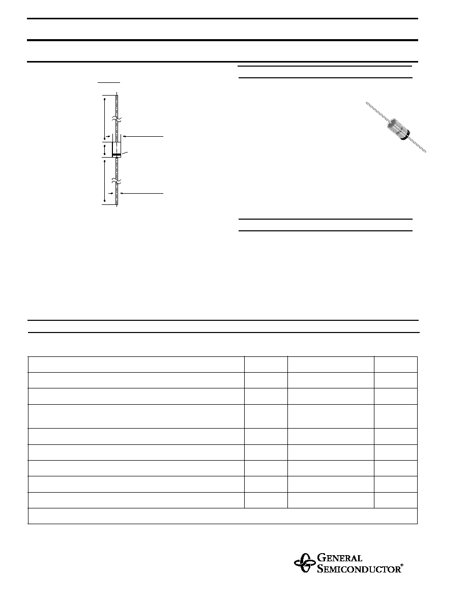
MECHANICAL DATA
MAXIMUM RATINGS AND ELECTRICAL CHARACTERISTICS
Ratings at 25 ∞C
ambient temperature unless otherwise specified
DO-35
mi
n. 1.083 (
27.5)
mi
n. 1.083
(
2
7
.
5)
max
.
.
150 (
3
.8)
max.
Cathode
.020 (0.52)
Mark
max.
.079 (2.0)
Dimensions in inches and (millimeters)
Case: DO-35 Glass Case
Weight: approx. 0.13 g
4/98
BAT42, BAT43
Symbol
Value
Unit
Repetitive Peak Reverse Voltage
V
RRM
30
V
Forward Continuous Current at T
amb
= 25 ∞C
I
F
200
1)
mA
Repetitive Peak Forward Current
at t
p
< 1 s,
< 0.5, T
amb
= 25 ∞C
I
FRM
500
1)
mA
Surge Forward Current at t
p
< 10 ms, T
amb
= 25 ∞C
I
FSM
4
1)
A
Power Dissipation
1)
at T
amb
= 65 ∞C
P
tot
200
1)
mW
Junction Temperature
T
j
125
∞C
Ambient Operating Temperature Range
T
amb
≠65 to +125
∞C
Storage Temperature Range
T
S
≠65 to +150
∞C
1)
Valid provided that leads at a distance of 4 mm from case are kept at ambient temperature
For general purpose applications
These diodes feature very low turn-
on voltage and fast switching. These
devices are protected by a PN junction
guard ring against excessive voltage, such
as electrostatic discharges.
These diodes are also available in the SOD-123
case with the type designations BAT42W to BAT43W
and in the MiniMELF case with type
designations LL42 to LL43.
ELECTRICAL CHARACTERISTICS
Ratings at 25 ∞C
ambient temperature unless otherwise specified
BAT42, BAT43
Symbol
Min.
Typ.
Max.
Unit
Reverse Breakdown Voltage
tested with 100
µ
A Pulses
V
(BR)R
30
≠
≠
V
Forward Voltage
Pulse Test t
p
< 300
µ
s,
< 2%
at I
F
= 200 mA
at I
F
= 10 mA
BAT42
at I
F
= 50 mA
BAT42
at I
F
= 2 mA
BAT43
at I
F
= 15mA
BAT43
V
F
V
F
V
F
V
F
V
F
≠
≠
≠
0.26
≠
≠
≠
≠
≠
≠
1
0.4
0.65
0.33
0.45
V
V
V
V
V
Leakage Current
Pulse Test t
p
< 300
µ
s,
< 2%
at V
R
= 25 V
at V
R
= 25 V, T
j
= 100 ∞C
I
R
I
R
≠
≠
≠
≠
0.5
100
µ
A
µ
A
Capacitance
at V
R
= 1 V, f = 1 MHz
C
tot
≠
7
≠
pF
Reverse Recovery Time
from I
F
= 10 mA through I
R
= 10 mA to I
R
= 1 mA,
R
L
= 100
t
rr
≠
≠
5
ns
Detection Efficiency
at R
L
= 15 K
, C
L
= 300 pF,
f = 45 MHz, V
RF
= 2 V
v
80
≠
≠
%
Thermal Resistance Junction to Ambient Air
R
thJA
≠
≠
0.3
1)
K/mW
1)
Valid provided that leads at a distance of 4 mm from the case are kept at ambient temperature