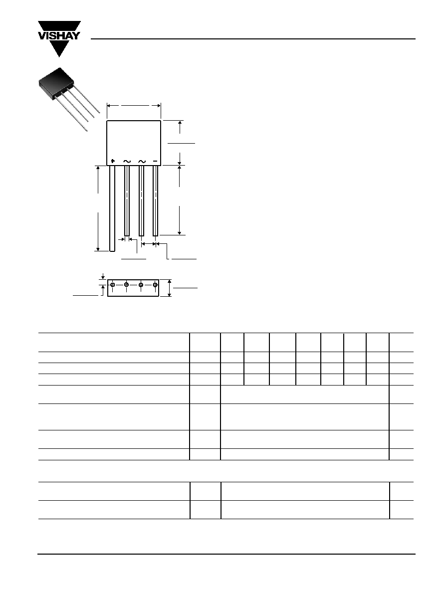
KBL005 thru KBL10
Vishay Semiconductors
formerly General Semiconductor
Document Number 88655
www.vishay.com
07-Oct-02
1
Single-Phase Bridge Rectifier
Reverse Voltage 50 and 1000 V
Forward Current 4.0 A
0.755 (19.18)
0.745 (18.92)
0.052 (1.32)
0.048 (1.22)
0.220 (5.59)
0.180 (4.57)
0.081 (2.06)
0.085 (2.18)
0.255 (6.48)
0.245 (6.22)
DIA.
1.1
(27.94)
MIN.
0.630 (16.0)
0.620 (15.75)
1.0
(25.4)
MIN.
Maximum Ratings & Thermal Characteristics
Ratings at 25∞C ambient temperature unless otherwise specified.
KBL
KBL
KBL
KBL
KBL
KBL
KBL
Symbols 005
01
02
04
06
08
10
Units
Maximum repetitive peak reverse voltage
V
RRM
50
100
200
400
600
800
1000
V
Maximum RMS voltage
V
RMS
35
70
140
280
420
560
700
V
Maximum DC blocking voltage
V
DC
50
100
200
400
600
800
1000
V
Maximum average forward output
current at T
A
=50∞C
I
F(AV)
4.0
A
Peak forward surge current single
sine-wave superimposed on rated load
I
FSM
200
A
(JEDEC Method) T
J
=150∞C
Typical thermal resistance per leg
(NOTE 1)
R
JA
19
(NOTE 2)
R
JL
2.4
∞C/W
Operating junction storage and temperature range T
J,
T
STG
-50 to +150
∞C
Electrical Characteristics
Ratings at 25∞C ambient temperature unless otherwise specified.
Maximum instantaneous forward drop per leg
at 4.0 A
V
F
1.1
V
Maximum DC reverse current at rated T
A
= 25∞C
5.0
µ
A
DC blocking voltage per leg
T
A
=125∞C
I
R
1.0
mA
Notes:
(1) Thermal resistance from junction to ambient with units mounted on 3.0 x 3.0 x 0.11" thick (7.5 x 7.5 x 0.3cm) Al. plate
(2) Thermal resistance from junction to lead with units mounted on P.C.B. at 0.375" (9.5mm) lead length and 0.5 x 0.5" (12 x 12mm) copper pads
Dimensions in inches and (millimeters)
Features
∑ Plastic package has Underwriters Laboratory
Flammability Classification 94V-0
∑ This series is UL listed under the Recognized
Component Index, file number E54214
∑ High case dielectric strength of 1500 V
RMS
∑ Ideal for printed circuit boards
∑ High forward surge current capability
∑ High surge current capability
∑ High temperature soldering guaranteed:
260∞C/10 seconds, 0.375 (9.5mm) lead length,
5lbs. (2.3kg) tension
Mechanical Data
Case: Molded plastic body
Terminals: Plated leads solderable per MIL-STD-750,
Method 2026
Mounting Position: Any
Weight: 0.2 oz., 5.6 g
Packaging codes/options:
1/300 EA. per Bulk Tray Stack
Case Style KBL

KBL005 thru KBL10
Vishay Semiconductors
formerly General Semiconductor
www.vishay.com
Document Number 88655
2
07-Oct-02
Ratings and
Characteristic Curves
(T
A
= 25∞C unless otherwise noted)
Temperature (
∞
C)
Fig. 1 ≠ Derating Curve
Output Rectified Current
A
verage Forward Current (A)
Fig. 3 ≠ Typical Instantaneous
Forward Characteristics Per Leg
Instantaneous Forward Voltage (V)
Instantaneous Forward Current (A)
Percent of Rated Peak Reverse Voltage (%)
Instantaneous Reverse Current (
µ
A)
Fig. 4 ≠ Typical Reverse Leakage
Characteristics Per Leg
Number of Cycles at 60 H
Z
Fig. 2 ≠ Maximum Non-Repetitive Peak
Forward Surge Current Per Leg
Peak Forward Surge Current (A)
Reverse Voltage (V)
Junction Capacitance, pF
Fig. 5 ≠ Typical Junction
Capacitance Per Leg
0
50
100
150
0
1.0
2.0
3.0
4.0
1
10
100
25
50
75
100
125
150
175
200
0.6
0.7
100
1.0
1
0.1
0.8
0.9
1.0
1.1
1.2
1.3
0
20
40
60
80
100
0.01
0.1
1
10
0.1
1
10
100
0
50
100
150
200
250
T
J
= 100
∞
C
T
J
= 25
∞
C
P.C.B. Mounting
0.375" (9.5mm) Lead Length
60 H
Z
Resistive or Inductive Load
Heatsink Mounted
3.0" sq. x 0.06" Thk
(7.5 x 0.15cm) Copper Plate
1.0 Cycle
T
J
= 150
∞
C
Single Sine-Wave
(JEDEC Method)
T
J
= 25
∞
C
Pulse Width = 300
µ
s
1% Duty Cycle
T
J
= 25
∞
C
f = 1.0MH
Z
Vsig = 50mVp-p