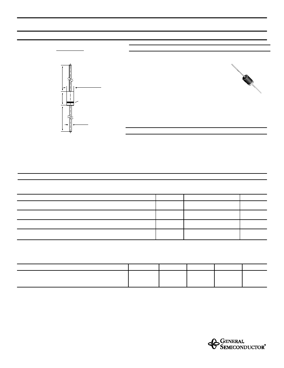
MECHANICAL DATA
Case: DO-41 Plastic Case
Weight: approx. 0.34 g
MAXIMUM RATINGS
Ratings at 25∞C ambient temperature unless otherwise specified.
SYMBOL
VALUE
UNIT
Zener Current (see Table "Characteristics")
Power Dissipation at Tamb = 25∞C
P
tot
2.0
1)
Watts
Junction Temperature
T
j
150
∞C
Storage Temperature Range
T
S
≠ 55 to +150
∞C
ZY1, ZY11 THRU ZY200
ZENER DIODES
12/16/98
SYMBOL
MIN.
TYP.
MAX.
UNIT
Thermal Resistance
R
thJA
≠
≠
60
1)
∞C/W
Junction to Ambient Air
NOTES:
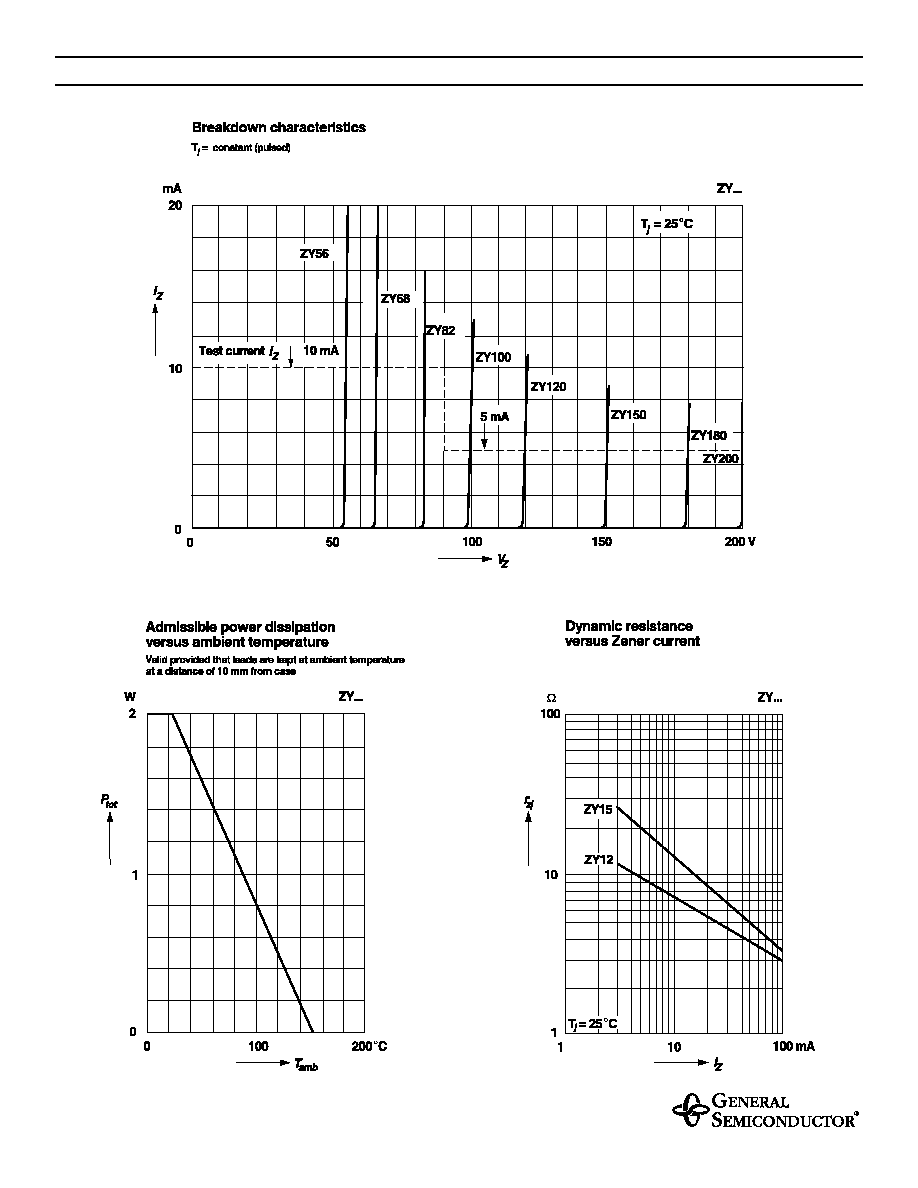
(1) Valid provided that leads are kept at ambient temperature at a distance of 10 mm from case.
FEATURES
Silicon Power Zener Diodes
For use in stabilizing and clipping circuits
with high power rating
The Zener voltages are graded according to the
international E 24 standard. Smaller voltage toler-
ances are available upon request.
mi
n
.
1.0 (
25.4)
ma
x.
0
.
2
0
(5
.
2
)
max.
Cathode
0.035 (0.9)
Mark
max.
0.11 (2.7)
mi
n. 1
.
0 (
2
5.4)
DO-41 Plastic
Dimensions are in inches and (millimeters)
ZY1, ZY11 THRU ZY200
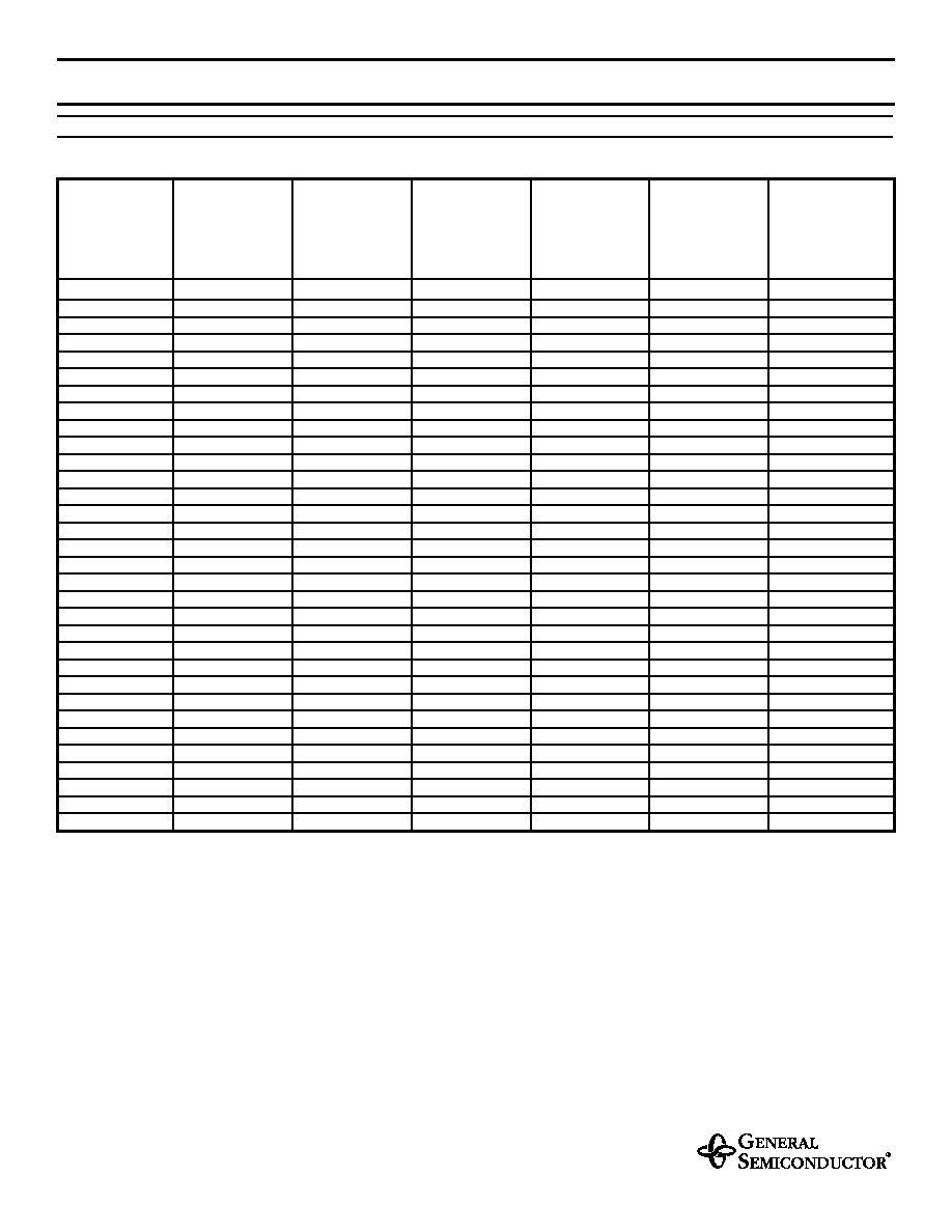
ELECTRICAL CHARACTERISTICS
Ratings at 25∞C ambient temperature unless otherwise specified.
Type
Zener
voltage
(2)
at
I
ZT
V
Z
(V)
Dynamic
resistance
at I
ZT
f = 1 kHz
max
r
zj
(
)
Temp. coeff.
of Zener volt.
at
I
ZT
VZ
(10
≠4
/ K)
Test
current
I
ZT
(mA)
Reverse
voltage
at
I
R
= 0.5
µ
A
V
R
(V)
Admissible
Zener current
(1)
at T
amb
= 25∞C
I
Z
(mA)
ZY1
(3)
0.71 ... 0.82
0.5 (< 1)
-26 ... -16
100
_
1000
ZY11
10.4 ... 11.6
4 (< 7)
+5 ... +10
50
> 9.2
135
ZY12
11.4 ... 12.7
4 (< 7)
+5 ... +10
50
> 10
120
ZY13
12.4 ... 14.1
5 (< 10)
+5 ... +10
50
> 10.7
110
ZY15
13.8 ... 15.8
5 (< 10)
+5 ... +10
50
> 12
98
ZY16
15.3 ... 17.1
6 (< 15)
+6 ... +11
25
> 13.3
90
ZY18
16.8 ... 19.1
6 (< 15)
+6 ... +11
25
> 14.7
80
ZY20
18.8 ... 21.2
6 (< 15)
+6 ... +11
25
> 16.5
72
ZY22
20.8 ... 23.3
6 (< 15)
+6 ... +11
25
> 18.3
66
ZY24
22.8 ... 25.6
7 (< 15)
+6 ... +11
25
> 20.1
60
ZY27
25.1 ... 28.9
7 (< 15)
+6 ... +11
25
> 22.5
53
ZY30
28 ... 32
8 (< 15)
+6 ... +11
25
> 25.1
48
ZY33
31 ... 35
8 (< 15)
+6 ... +11
25
> 27.8
44
ZY36
34 ... 38
21 (< 40)
+6 ... +11
10
> 30.2
40
ZY39
37 ... 41
21 (< 40)
+6 ... +11
10
> 32.9
37
ZY43
40 ... 46
24 (< 45)
+7 ... +12
10
> 35.6
33
ZY47
44 ... 50
24 (< 45)
+7 ... +12
10
> 39.2
30
ZY51
48 ... 54
25 (< 60)
+7 ... +12
10
> 42.8
27
ZY56
52 ... 60
25 (< 60)
+7 ... +12
10
> 47.3
25
ZY62
58 ... 66
25 (< 80)
+8 ... +13
10
> 51.7
21
ZY68
64 ... 72
25 (< 80)
+8 ... +13
10
> 57.1
20
ZY75
70 ... 79
30 (< 100)
+8 ... +13
10
> 63.2
18
ZY82
77 ... 88
30 (< 100)
+8 ... +13
10
> 68.6
16
ZY91
85 ... 96
60 (< 200)
+9 ... +13
5
> 75.7
15
ZY100
94 ... 106
60 (< 200)
+9 ... +13
5
> 83.7
13
ZY110
104 ...116
80 (< 250)
+9 ... +13
5
> 92.6
12
ZY120
114 ... 127
80 (< 250)
+9 ... +13
5
> 101.6
11
ZY130
124 ... 141
110 (< 300)
+9 ... +13
5
> 110.5
10
ZY150
138 ... 156
110 (< 300)
+9 ... +13
5
> 123
9
ZY160
153 ...171
150 (< 350)
+9 ... +13
5
>136
8.5
ZY180
168 ... 191
150 (< 350)
+9 ... +13
5
> 149
8
ZY200
188 ... 212
150 (< 350)
+9 ... +13
5
> 167
7.5
NOTES:
(1) Valid provided that leads are kept at ambient temperature at a distance of 10 mm from case
(2) Tested with pulses t
p
= 5 ms
(3) The ZY1 is a silicon diode operated in forward direction. Hence, the index of all parameters ratings should be "F" instead of "Z". Connect the cathode lead to the
negative pole