 | –≠–ª–µ–∫—Ç—Ä–æ–Ω–Ω—ã–π –∫–æ–º–ø–æ–Ω–µ–Ω—Ç: GS3044 | –°–∫–∞—á–∞—Ç—å:  PDF PDF  ZIP ZIP |
DATA SHEET
AGC-O with Active Low Cut Filter
in a CIC Size Hybrid - GS3044
FEATURES
∑ CIC suitable package size
∑
low distortion compression limiting
∑
38dB maximum system gain, adjustable over a
38dB range
∑
output compression threshold, adjustable over
16dB range
∑
2nd order active low cut filter adjustable from 530Hz
to 2.0kHz
∑
designed to drive a class D integrated receiver
∑
averaging detector
∑
flexibility to add high cut filter
STANDARD PACKAGING
Hybrid typical dimensions:
0.180 x 0.110 x 0.070 in.
(4.57 x 2.79 x 1.78 mm)
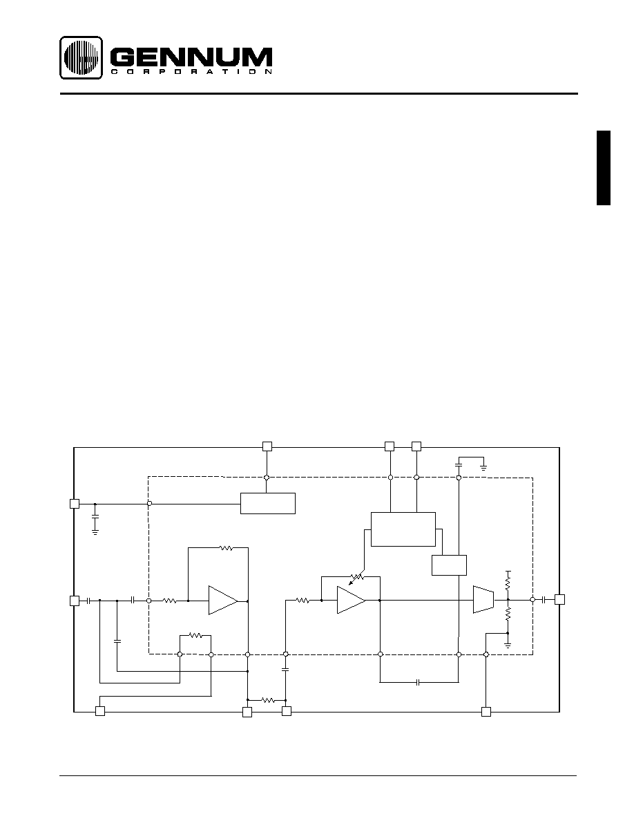
DESCRIPTION
The GS3044 CIC hybrid features AGC-O capability for low
distortion output limiting with an active low cut filter in a
package size suitable for CIC instruments. The circuit consists
of an AGC preamplifier and output stage, capable of driving
a class D integrated receiver. The compression control circuit,
connected between the input and output of the AGC
preamplifier, varies the current controlled resistance. It
operates with an 8:1 compression ratio and uses an averaging
detector with a time constant of 270ms, selected to provide
optimal sound quality over a full range of sound and listening
environments. The actual attack and release times are typically
40ms and 150ms respectively when the circuit is fully in the
compression region of operation (measured times vary
depending on gain and threshold settings).
The system gain, compression control and filter corner
frequency can be adjusted by choosing three independent
resistors or 100k trimmers. Maximum system gain is 38dB. It
can be adjusted within a 38dB range. The output compression
threshold can be adjusted within a 16dB range. The filter's
corner frequency can be adjusted from 530Hz to 2kHz.
BLOCK DIAGRAM
Revision Date: March 2000
C2
0
µ
1
C5
0
µ
1
C7
0
µ
15
C8
33n
12k
48k
VB
REGULATOR
48k
-A
RECT.
B
8:1
COMPRESSION
CONTROL
C6
22n
R
VC
R
TH
-F
C1
15n
C3
6n8
C4
10n
R
HP
10k
80k
800
IN
F
OUT
A
IN
GND
V
REG
V
B
OUT
GS3044
R1 = 0
Note: R1 can be desoldered from hybrid to break connection between F
OUT
and A
IN
10
1
4
5
6
7
8
9
3
2
All resistors in ohms, all capacitors
in farad, unless otherwidse stated.
GENNUM CORPORATION P.O. Box 489, Stn. A, Burlington, Ontario, Canada L7R 3Y3 tel. +1 (905) 632-2996
Web Site: www.gennum.com E-mail: hipinfo@gennum.com
Document No. 521 - 90 - 02
GS3044

2
521 - 90 -02
GS3044
PAD CONNECTION
CONDITIONS: Frequency = 1 kHz, Temperature = 25
∞
C, Supply Voltage V
B
= 1.3 V
ELECTRICAL CHARACTERISTICS
V
B
V
REG
R
VC
OUT
IN
R
TH
GND
R
HP
1 2 3 4 5
6
10
9 8
7
F
OUT
A
IN
R
E
T
E
M
A
R
A
P
L
O
B
M
Y
S
S
N
O
I
T
I
D
N
O
C
N
I
M
P
Y
T
X
A
M
S
T
I
N
U
t
n
e
r
r
u
C
d
i
r
b
y
H
I
P
M
A
-
5
3
2
0
4
3
A
µ
e
g
a
t
l
o
V
m
u
m
i
n
i
M
V
B
-
-
1
.
1
V
n
o
i
t
r
o
t
s
i
D
c
i
n
o
m
r
a
H
l
a
t
o
T
D
H
T
V
N
I
V
B
d
0
6
-
=
-
5
.
0
0
.
1
%
e
s
i
o
N
d
e
r
r
e
f
e
R
t
u
p
n
I
N
R
I
R
,
d
e
t
h
g
i
e
w
A
P
H
k
0
0
1
=
-
4
.
4
-
V
µ
S
M
R
k
a
e
P
t
a
n
i
a
G
m
e
t
s
y
S
A
V
R
,
z
H
k
8
.
2
=
y
c
n
e
u
q
e
r
F
P
H
k
0
0
1
=
5
3
8
3
1
4
B
d
,
t
u
C
w
o
L
h
t
i
w
k
a
e
P
t
a
n
i
a
G
e
v
i
t
a
l
e
R
3
e
t
o
N
A
V
R
,
z
H
k
8
.
2
=
y
c
n
e
u
q
e
r
F
P
H
0
=
-
0
.
1
-
-
B
d
3
e
t
o
N
,
z
H
0
0
5
t
a
n
i
a
G
e
v
i
t
a
l
e
R
A
F
L
R
,
z
H
0
0
5
=
y
c
n
e
u
q
e
r
F
P
H
k
0
0
1
=
-
0
.
3
-
-
B
d
,
t
u
C
w
o
L
h
t
i
w
z
H
0
0
5
t
a
n
i
a
G
e
v
i
t
a
l
e
R
3
e
t
o
N
A
C
L
R
,
z
H
0
0
5
=
y
c
n
e
u
q
e
r
F
P
H
0
=
7
2
-
3
2
-
9
1
-
B
d
3
e
t
o
N
,
z
H
k
5
t
a
n
i
a
G
e
v
i
t
a
l
e
R
A
F
H
R
,
z
H
k
5
=
y
c
n
e
u
q
e
r
F
P
H
k
0
0
1
=
-
0
.
3
-
-
B
d
e
g
a
t
l
o
V
r
o
t
a
l
u
g
e
R
V
G
E
R
0
9
8
5
3
9
0
0
0
1
V
m
o
i
t
a
R
n
o
i
t
c
e
j
e
R
y
l
p
p
u
S
r
e
w
o
P
R
R
S
P
9
4
6
5
-
B
d
C
G
A
)
d
e
r
r
e
f
e
R
P
/
O
(
d
l
o
h
s
e
r
h
T
m
u
m
i
x
a
M
H
T
X
A
M
V
N
I
2
e
t
o
N
,
V
B
d
0
6
-
=
3
4
-
1
4
-
9
3
-
V
B
d
)
d
e
r
r
e
f
e
R
P
/
O
(
d
l
o
h
s
e
r
h
T
m
u
m
i
n
i
M
H
T
N
I
M
V
N
I
R
,
V
B
d
0
7
-
=
H
T
2
e
t
o
N
,
k
0
0
1
=
9
5
-
7
5
-
5
5
-
V
B
d
e
g
n
a
R
n
i
a
G
C
V
A
C
V
R
C
V
k
0
0
1
=
0
o
t
5
3
8
3
1
4
B
d
d
l
o
h
s
e
r
h
T
h
g
i
H
o
i
t
a
R
n
o
i
s
s
e
r
p
m
o
C
H
-
P
M
C
V
N
I
R
,
V
B
d
0
3
-
o
t
V
B
d
0
6
-
=
H
T
0
=
0
.
8
0
.
9
0
.
0
1
o
i
t
a
r
d
l
o
h
s
e
r
h
T
w
o
L
o
i
t
a
R
n
o
i
s
s
e
r
p
m
o
C
L
-
P
M
C
V
N
I
R
,
V
B
d
0
4
-
o
t
V
B
d
0
7
-
=
H
T
k
0
0
1
=
5
.
6
3
.
7
0
.
9
o
i
t
a
r
n
i
a
G
A
e
g
a
t
S
A
A
V
N
I
V
B
d
0
7
-
=
4
2
7
2
0
3
B
d
e
g
n
a
R
n
i
a
G
n
o
i
s
s
e
r
p
m
o
C
A
E
G
N
A
R
1
e
t
o
N
7
4
3
5
5
5
B
d
t
n
a
t
r
s
n
o
C
e
m
i
T
C
G
A
C
G
A
-
0
7
2
-
s
m
E
G
A
T
S
T
U
P
T
U
O
n
i
a
G
A
B
-
1
1
-
B
d
e
c
n
a
t
s
i
s
e
R
t
u
p
t
u
O
R
P
O
-
4
2
-
k
R
E
T
L
I
F
y
c
n
e
u
q
e
r
F
r
e
n
r
o
C
m
u
m
i
n
i
M
_
C
N
I
M
-
0
3
5
-
z
H
y
c
n
e
u
q
e
r
F
r
e
n
r
o
C
m
u
m
i
x
a
M
_
C
X
A
M
-
2
-
z
H
k
All parameters and switches remain as shown in the Test Circuit unless otherwise stated in the CONDITIONS column.
NOTE:
1. A
RANGE
= A
A
- A
A
[V
IN
= -20dBV, R
TH
= 100k]
2. Measured at output of Stage A
3. Relative to System Gain at Peak
CAUTION
ELECTROSTATIC
SENSITIVE DEVICES
DO NOT OPEN PACKAGES OR HANDLE
EXCEPT AT A STATIC-FREE WORKSTATION
ABSOLUTE MAXIMUM RATINGS
PARAMETER
VALUE
Supply Voltage
3 VDC
Power Dissipation
25 mW
Operating Temperature Range
-10
∞
C to 40
∞
C
Storage Temperature Range
-20
∞
C to 70
∞
C

521 - 90 - 02
3
GS3044
50k
V
OUT
V
IN
V
B
Rvc=100k
R
TH
=0
RHP
100k
C2
0
µ
1
C5
0
µ
1
C7
0
µ
15
C8
33n
12k
48k
VB
REGULATOR
48k
-A
RECT.
B
8:1
COMPRESSION
CONTROL
C6
22n
-F
C1
15n
C3
6n8
C4
10n
10k
80k
800
F
OUT
A
IN
V
REG
GS3044
R1 = 0
10
1
4
5
6
7
8
9
3
2
All resistors in ohms, all capacitors
in farad, unless otherwidse stated.
3k9
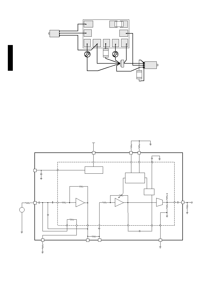
Fig. 1 Production Test Circuit
2
µ
2
Any Knowles
class D
integrated
receiver
Any
Knowles
or
Microtronic
Microphone
VB
V
B
R
vc
R
TH
C2
0
µ
1
C5
0
µ
1
C7
0
µ
15
C8
33n
48k
V
B
REGULATOR
48k
-A
RECT.
B
8:1
COMPRESSION
CONTROL
C6
22n
100k
(Log)
100k
(Log)
100k
(Log)
-F
R
HP
GS3044
R1 = 0
12k
C1
15n
C3
6n8
C4
10n
10k
80k
800
10
1
4
5
6
7
8
9
3
2
All resistors in ohms, all capacitors
in farad, unless otherwidse stated.
Fig. 2 Typical Application Circuit
4
521 - 90 -02
GS3044
Fig. 4 Characterization Circuit (used to generate typical curves)
Fig. 3 Typical Hearing Instrument Assembly Diagram
+
BATTERY
R
VC
5 4 3 2 1
6
10
9
8
7
+
RECEIVER
MIC
+
-
R
TH
R
HP
2
µ
2
R1
3k9
Pink
Noise
Generatoror
1kHz for I/O
50k
V
OUT
1.3V
Rvc=100k
R
TH
=100k
C2
0
µ
1
C5
0
µ
1
C7
0
µ
15
C8
33n
48k
VB
REGULATOR
48k
-A
RECT.
B
8:1
COMPRESSION
CONTROL
C6
22n
-F
RHP
100k
GS3044
R1 = 0
12k
C1
15n
C3
6n8
C4
10n
10k
80k
800
AIN
10
1
4
5
6
7
8
9
3
2
All resistors in ohms, all capacitors
in farad, unless otherwidse stated.
521 - 90 - 02
5
GS3044
0
1
2
3
4
5
6
100
1k
10k
THD (%)
FREQUENCY (kHz)
R
TH
= 0
R
TH
= 100k
V
IN
= -40dBV
R
VC
= 100k
0
5
10
15
20
25
30
35
40
45
100
1k
10k
FREQUENCY (kHz)
GAIN (dB)
R
HP
= 0
R
HP
= 100k
R
TH
= 0
R
VC
= 100k
V
IN
= -70dBV
-70
-65
-60
-55
-50
-45
-40
-35
-30
-25
-20
-140
-120
-100
-80
-60
-40
-20
0
INPUT (dBV)
OUTPUT (dBV)
R
VC
= 100k
V
IN
=1kHz
R
TH
=25k
R
TH
=100k
R
TH
=0
-95
-90
-85
-80
-75
-70
-65
-60
-55
-50
-45
-40
-35
-30
-25
-20
-15
-140
-120
-100
-80
-60
-40
-20
0
INPUT (dBV)
OUTPUT (dBV)
0
1.5k
4.75k
12.1k
25k
50k
R
VC
= 100k
V
IN
= 1kHz
R
TH
=0
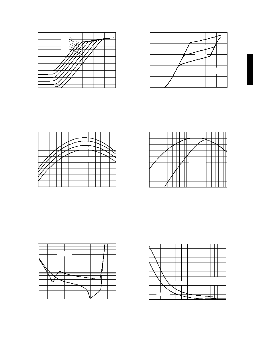
Fig. 5 Input vs Output Volume Control Settings
Fig. 6 Input vs Output Threshold Settings
Fig. 7 Frequency Response vs R
TH
Fig. 8 Frequency Response vs R
HF
Fig. 9 THD vs Input
0.1
1
10
-90
-80
-70
-60 -50
-40
-30
-20
-10
0
INPUT (dBV)
THD (%)
R
VC
= 100k
V
IN
= 1kHz
R
TH
= 100k
R
TH
= 0
Fig. 10 THD vs Frequency
TYPICAL PERFORMANCE CURVES
0
5
10
15
20
25
30
35
40
45
100
1k
10k
GAIN (dB)
FREQUENCY (kHz)
R
VC
= 100k
V
IN
= -70dBV
R
TH
=0
R
TH
=100k
R
TH
=25k
R
TH
=50k
6
521 - 90 -02
GS3044
IMD (%)
V
IN
=1kHz
R
VC
=100k
R
TH
= 0
0.01
0.1
-80
-70
-60
-50
-40
-30
-20
-10
0
INPUT (dBV)
Gennum Corporation assumes no responsibility for the use of any circuits described herein and makes no representations that they are free from patent infringement.
© Copyright September 1998 Gennum Corporation. All rights reserved. Printed in Canada.
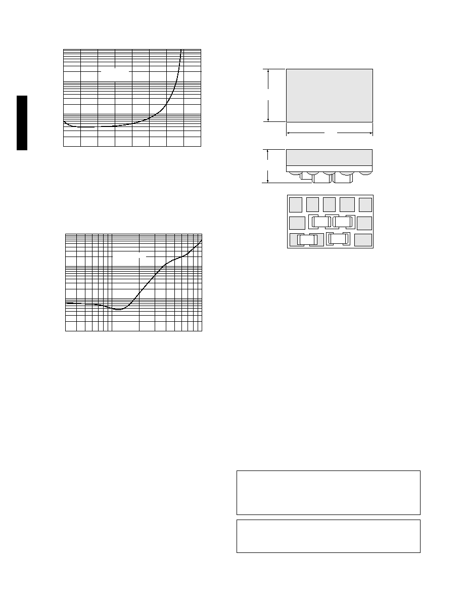
Fig. 12 Intermodulation Distortion vs Frequency
Fig. 11 Intermodulation distortion vs Input
0.01
0.1
1
10
10k
100k
R
TH
= 0
FREQUENCY (kHz)
IMD (%)
V
IN
-40dBV
3k
R
VC
=100k
PACKAGE DIMENSIONS
DOCUMENT IDENTIFICATION:
DATA SHEET
The product is in production. Gennum reserves the right to make
changes at any time to improve reliability, function or design, in
order to provide the best product possible.
GENNUM CORPORATION
MAILING ADDRESS:
P.O. Box 489, Stn. A, Burlington, Ontario, Canada L7R 3Y3
Tel. +1 (905) 632-2996 Fax +1 (905) 632-2814
SHIPPING ADDRESS:
970 Fraser Drive, Burlington, Ontario, Canada L7L 5P5
GENNUM JAPAN CORPORATION
C-101, Miyamae Village, 2-10-42 Miyamae, Suginami-ku, Tokyo 168-0081, Japan
Tel. +81 (3) 3334-7700 Fax: +81 (3) 3247-8839
REVISION NOTES:
Updated to Data Sheet; Correction to Figure 7.
GS3044
XXXXXX
0.110
(2.79)
0.079 MAX
(2.01)
1 2 3 4 5
6
10
R1
9
8
7
0.180
(4.57)
C4
C1
C3
Dimensions are in inches.
Dimensions shown in parenthesis are in millimeters, converted
from inches and include minor rounding errors.
1.0000 inches = 25.400mm.
Dimension tolerances
±
0.003 (+0.08) unless otherwise stated.
Minimum Pad size: 0.027 x 0.026in (0.68 x 0.71mm)
XXXXXX - work order number.
This hybrid is designed for point-to-point manual soldering.