 | –≠–ª–µ–∫—Ç—Ä–æ–Ω–Ω—ã–π –∫–æ–º–ø–æ–Ω–µ–Ω—Ç: GS9023A | –°–∫–∞—á–∞—Ç—å:  PDF PDF  ZIP ZIP |
GENNUM CORPORATION P.O. Box 489, Stn. A, Burlington, Ontario, Canada L7R 3Y3
Tel. +1 (905) 632-2996 Fax. +1 (905) 632-5946 E-mail: info@gennum.com
www.gennum.com
Revision Date: May 2004
Document No. 19795 - 6
DATA SHEET
GS9
023
A
KEY FEATURES
∑ single chip embedded audio solution
∑ operates as an embedded audio multiplexer or
demultiplexer
∑ full support for 48kHz synchronous 20/24 bit audio
∑ 4 channels of audio per GS9023A
∑ cascadable architecture supports additional audio
channels
∑ multiplexes and demultiplexes arbitrary ANC data
packets
∑ support for 143, 177, 270, 360 and 540 Mb/s video
standards
∑ full processing of audio parity, channel status and
user data
∑ multiplexes and demultiplexes audio control packets
∑ EDH generation and insertion when in Multiplex Mode
∑ 3.3V core with 3.3V or 5V I/O (requires 5V supply)
∑ complies with SMPTE 272M A, B, and C
APPLICATIONS
SDI Embedded Audio
BRIEF DESCRIPTION
The GS9023A is a highly integrated, single chip solution for
the multiplexing/demultiplexing of digital audio channels
into and out of digital video signals. The GS9023A supports
the multiplexing/demultiplexing of 20 or 24-bit synchronous
audio data with a 48kHz sample rate.
Audio signals with different sample rates may be sample
rate converted to 48kHz before and after the GS9023A
using audio sample rate converters.
Each GS9023A supports all the processing required to
handle the multiplexing/demultiplexing of four digital audio
channels. To simplify system design, the GS9023A
seamlessly integrates with common AES/EBU digital audio
receivers and transmitters. The cascadable architecture
allows for the multiplexing/demultiplexing of additional
audio channels with no external glue logic.
The GS9023A supports video standards with rates from
143Mb/s to 540Mb/s. When in Multiplex Mode, the
GS9023A supports the generation and insertion of EDH
information according to SMPTE RP165. In combination with
Gennum's GS9032, the GS9023A provides a low power,
highly integrated two chip solution for SDI transmit
applications. In combination with Gennum's GS7005, the
GS9023A provides a low power, highly integrated two chip
solution for SDI receive applications.
The GS9023A requires a 3.3V power supply for internal
core logic and a 3.3V or 5V power supply for device I/O.
ORDERING INFORMATION
PART NUMBER
PACKAGE
TEMPERATURE
GS9023ACFY
100 pin LQFP
0∞C to 70∞C
GENLINX
TM
II
GS9023A
Embedded Audio CODEC
2 of 37
GS9
023
A
GENNUM CORPORATION
19795 - 6
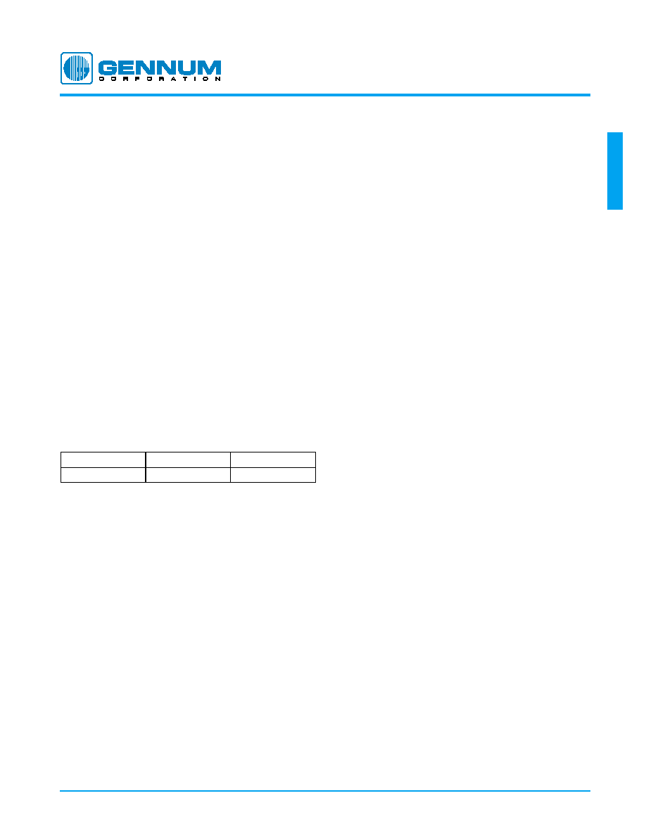
MULTIPLEX MODE BLOCK DIAGRAM
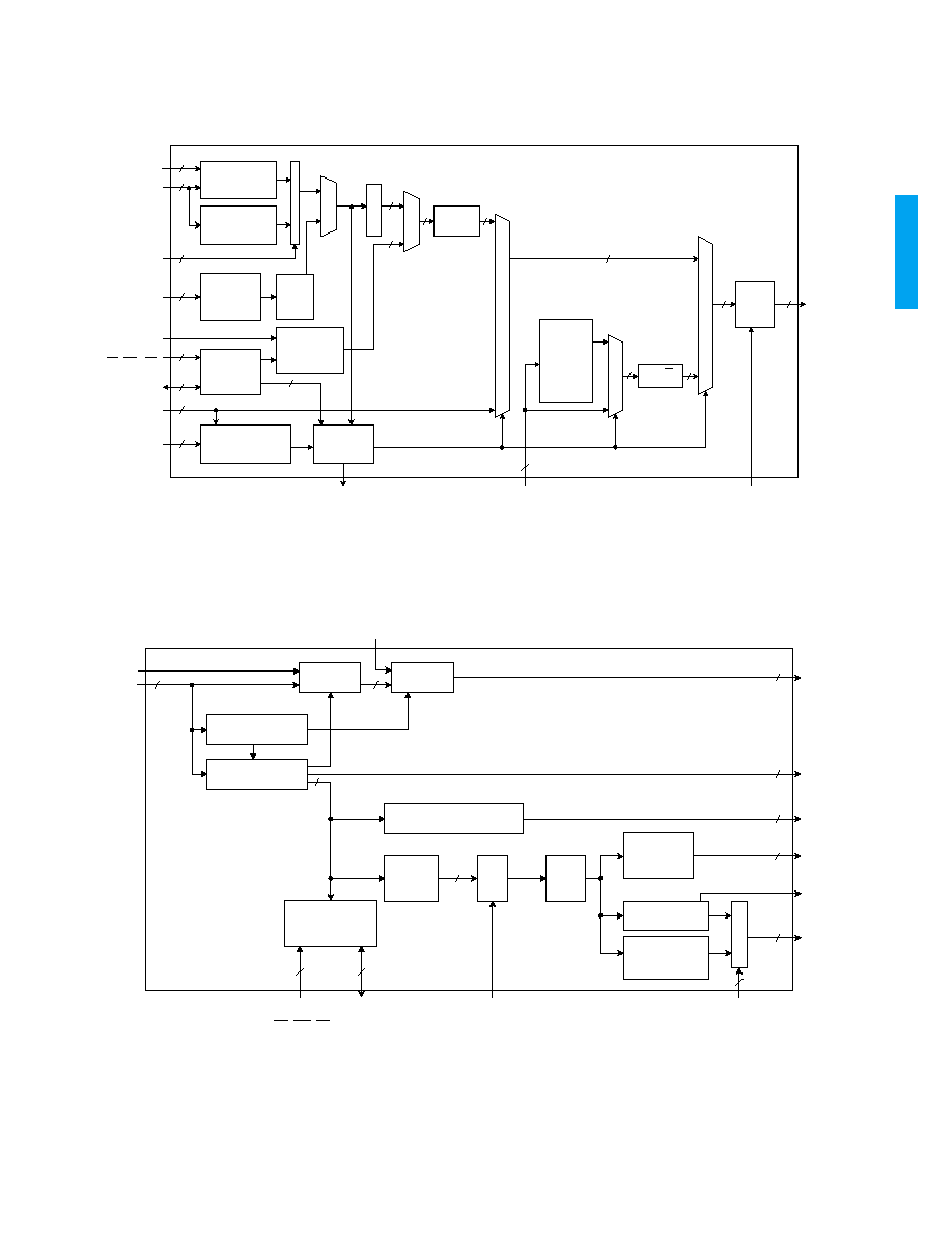
DEMULTIPLEX MODE BLOCK DIAGRAM
Convert Input
Data Format
Convert
AES/EBU
Format
WCINA/B
AINA/B
AUXEN
AM[2:0]
MPX
Convert
Control
Code
Add
CRC
SAFA/B
CSA/B
UDA/B
VFLA/B
S/P
MPX
Control
Registers
Generate
Audio
Packets
ADDR[3:0]
CS, WE, RE
DATA[7:0]
Audio
Buffer
MPX
DIN[9:0]
10
10
10
10
3
3
8
10
7
8
Generate
ANCI area
8
Video Detection
& Synchronization
VM[2:0]
LOCK
Arbitrary
Packet
Buffer
PKT[8:0]
MPX
9
b9=b8
9
MPX
10
10
Add
EDH
10
10 DOUT[9:0]
EDH_INS
MUTE
3
2
Convert Output
Data Format
Convert
AES/EBU
Format
ANCI
Output
Control
Code
Add
CRC
Control
Registers
DIN[9:0]
10
Video Detection &
Synchronization
10
DOUT[9:0]
Delete
ANCI
Delete
TRS
10
TRS
Detect ANCI
3
LOCK
BUFERR
AUXEN
AM[2:0]
AOUTA/B
8
SAFA/B
CSA/B
UDA/B
VFLA/B
P/S
Audio
Buffer
10
Output Arbitrary Packet
PKT[8:0]
9
10
WCOUT
ADDR[3:0],
CS, WE, RE
7
8
DATA[7:0]
MUTE
2
3

3 of 37
GS9
023
A
GENNUM CORPORATION
19795 - 6
CONTENTS
1. PIN CONNECTIONS............................................................................................................................ 4
2. DETAILED DESCRIPTION ..................................................................................................................... 8
2.1 MULTIPLEX MODE ............................................................................................................... 8
2.1.1 VIDEO CLOCK INPUT............................................................................................................................................8
2.1.2 VIDEO DATA INPUT...............................................................................................................................................8
2.1.3 VIDEO DATA OUTPUT...........................................................................................................................................9
2.1.4 AUDIO CLOCK INPUT ...........................................................................................................................................9
2.1.5 AUDIO DATA INPUT ..............................................................................................................................................9
2.1.6 CONTROL CODE INPUT .......................................................................................................................................9
2.1.7 AUDIO DATA PACKETS ......................................................................................................................................11
2.1.8 EXTENDED AUDIO DATA PACKETS ...................................................................................................................14
2.1.9 AUDIO CONTROL PACKETS...............................................................................................................................16
2.1.10 ARBITRARY DATA PACKETS ............................................................................................................................18
2.1.11 ERROR DETECTION ..........................................................................................................................................19
2.2 DEMULTIPLEX MODE ......................................................................................................... 19
2.2.1 VIDEO CLOCK INPUT..........................................................................................................................................19
2.2.2 VIDEO DATA INPUT.............................................................................................................................................19
2.2.3 VIDEO DATA OUTPUT.........................................................................................................................................20
2.2.4 AUDIO CLOCK INPUT .........................................................................................................................................21
2.2.5 AUDIO DATA OUTPUT ........................................................................................................................................21
2.2.6 CONTROL CODE OUTPUT..................................................................................................................................23
2.2.7 DETECTION OF AUDIO PACKETS ......................................................................................................................23
2.2.8 DETECTION OF EXTENDED AUDIO PACKETS ..................................................................................................24
2.2.9 DETECTION OF AUDIO CONTROL PACKETS ....................................................................................................24
2.2.10 DETECTION AND OUTPUT OF ARBITRARY DATA PACKETS..........................................................................24
2.2.11 ERROR DETECTION ..........................................................................................................................................24
2.3 MULTIPLEX AND DEMULTIPLEX MODES ............................................................................... 25
2.3.1 DELAY OF VIDEO AND AUDIO ...........................................................................................................................25
2.3.2 NON-STANDARD SAMPLE DISTRIBUTIONS ......................................................................................................25
2.3.3 HOST INTERFACE ...............................................................................................................................................25
2.3.4 RESET ..................................................................................................................................................................25
2.3.5 INTERCONNECTION WITH GS9032 OR GS7005 ...............................................................................................25
2.3.6 AUDIO CLOCK AND VIDEO CLOCK STABILITY IN MULTIPLEX MODE ............................................................25
2.3.7 INTERCONNECTION WITH GS9020 ...................................................................................................................25
3. HOST INTERFACE TABLES ............................................................................................................... 26
3.1 MULTIPLEX MODE ............................................................................................................. 26
3.2 DEMULTIPLEX MODE ........................................................................................................ 29
4. PACKAGING INFORMATION .............................................................................................................. 37
5. REVISION HISTORY .......................................................................................................................... 37
4 of 37
GS9
023
A
GENNUM CORPORATION
19795 - 6
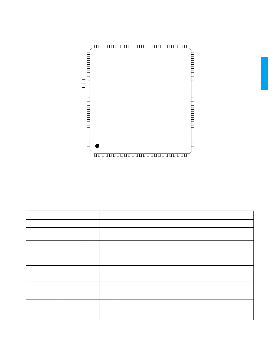
1. PIN CONNECTIONS
PCLK
DIN9
DIN8
DIN7
DIN6
DIN5
DIN4
DIN3
DIN1
D
OUT9
DIN2
DIN0
D
OUT0
D
OUT1
D
OUT2
D
OUT3
D
OUT4
D
OUT5
D
OUT6
D
OUT7
D
OUT8
WC
INA
WC
INB
VFLB
VFLA
A
OUTB
A
OUT
A
A
INB
A
INA
WC
OUT
AUXEN
SAFB
CSA
CSB
UDA
UDB
SAFA
MUTE
PKT2
PKT3
PKT8
PKT7
PKT6
PKT5
PKT4
PKT1
PKT0
NC
VM2
VM1
VM0
AM2
AM1
EDH_INS
TRS
ANCI
LOCK
NC
BUFERR
ADDR3
ADDR2
ADDR1
ADDR0
DATA7
DATA6
DATA5
DATA4
DATA3
D
ATA
2
D
ATA
0
D
ATA
1
1
9
8
7
6
5
4
3
2
10
27
26
24 25
28
23
22
21
20
19
18
17
16
15
14
13
12
11
37
36
35
34
33
32
31
30
29
50
49
48
47
46
45
44
43
42
41
40
39
38
75
67
68
69
70
71
72
73
74
66
52 51
53
54
55
56
57
58
59
60
61
62
63
64
65
99
100
98
89
90
91
92
93
94
95
96
97
76
77
78
79
80
81
82
83
84
85
86
87
88
GS9023A
(TOP VIEW)
GND
ACLK
GND
VDDINT
GND
V
DDIO
GND
V
DDIO
GND
PKTEN
VDDIO
GND
VDDINT
GND
VDDINT
GND
VDDINT
GND
TEST
TEST
VDDIO
AM0
TEST
GND
RESET
DEMUX/MUX
RE
WE
CS
NOTE: The GS9023A DOUT[9:0] MSB to LSB convention is compatible with
the GS9022 but reversed with the GS9032 or GS7005.
See Interconnection with GS9032 or GS7005 section.
PIN DESCRIPTIONS
NUMBER
SYMBOL
TYPE
DESCRIPTION
1, 17, 26, 90
VDDINT
+3.3V power supply pins for core logic.
2-4
VM[2:0]
I
Video standard format. Used in conjunction with the TRS pin. VM[2] is the MSB
and VM[0] is the LSB. See Table 1.
5
DEMUX/MUX
I
Mode of operation. When set HIGH, the GS9023A operates in Demultiplex Mode.
When set LOW, the GS9023A operates in Multiplex Mode.
NOTE: A device reset must be performed when switching between Multiplex and
Demultiplex Modes while the device is powered up.
6-10,12-16
DIN[9:0]
I
Parallel digital video signal input. DIN[9] is the MSB and DIN[0] is the
LSB. The digital video input must contain TRS information.
11, 23, 25, 29,
50, 58, 71, 82,
98, 100
GND
Device ground.
18
RESET
I
Device reset. Active low.
NOTE: The video input to output data path will be interrupted during device
reset.

5 of 37
GS9
023
A
GENNUM CORPORATION
19795 - 6
19
WCINA
I
48kHz word clock for channels 1 and 2. Used only when operating in Multiplex
Mode and when the audio source is not an AES/EBU data stream. This pin
should be grounded when inputting AES/EBU digital audio data or when
operating in Demultiplex Mode.
20
WCINB
I
48kHz word clock for channels 3 and 4. Used only when operating in Multiplex
Mode and when the audio source is not an AES/EBU data stream. This pin
should be grounded when inputting AES/EBU digital audio data or when
operating in Demultiplex Mode.
21
AINA
I
Audio signal input for channels 1 and 2. AES/EBU digital audio data is bi-phase
mark encoded. For all non-AES/EBU input modes, bi-phase mark encoding is not
required.
22
AINB
I
Audio signal input for channels 3 and 4. AES/EBU digital audio data is bi-phase
mark encoded. For all non-AES/EBU input modes, bi-phase mark encoding is not
required.
24
PCLK
I
Video clock signal input.
27, 28, 75
TEST
-
Connect to ground.
30
SAFA
I/O
Start of audio frame indicator for channels 1 and 2. Valid only for non-AES/EBU
audio formats. This pin should be grounded when inputting AES/EBU audio data.
SAFA is HIGH for audio frame 0 and LOW for all other audio frames. In Multiplex
Mode, this pin is an input and is supplied by the user. In Demultiplex Mode, this
pin is an output and is generated by the GS9023A.
31
SAFB
I/O
Start of audio frame indicator for channels 3 and 4. Valid only for non-AES/EBU
audio formats. This pin should be grounded when inputting AES/EBU audio data.
SAFB is set to HIGH for audio frame 0 and LOW for all other audio frames. In
Multiplex Mode, this pin is an input and is supplied by the user. In Demultiplex
Mode, this pin is an output and is generated by the GS9023A.
32
VFLA
I/O
Validity flag for channels 1 and 2. Valid only for non-AES/EBU audio formats. This
pin should be grounded when inputting AES/EBU audio data. VFLA is HIGH
when audio is invalid and LOW when audio is valid. In Multiplex Mode, this pin is
an input and is supplied by the user. In Demultiplex Mode, this pin is an output
and is generated by the GS9023A.
33
VFLB
I/O
Validity flag for channels 3 and 4. Valid only for non-AES/EBU audio formats. This
pin should be grounded when inputting AES/EBU audio data. VFLB is HIGH
when audio is invalid and LOW when audio is valid. In Multiplex Mode, this pin is
an input and is supplied by the user. In Demultiplex Mode, this pin is an output
and is generated by the GS9023A.
34
UDA
I/O
User data for channels 1 and 2. Valid only for non-AES/EBU audio formats. This
pin should be grounded when inputting AES/EBU audio data. In Multiplex Mode,
this pin is an input and is supplied by the user. In Demultiplex Mode, this pin is
an output and is generated by the GS9023A.
35
UDB
I/O
User data for channels 3 and 4. Valid only for non-AES/EBU audio formats. This
pin should be grounded when inputting AES/EBU audio data. In Multiplex Mode,
this pin is an input and is supplied by the user. In Demultiplex Mode, this pin is
an output and is generated by the GS9023A.
36
CSA
I/O
Channel status for channels 1 and 2. Valid only for non-AES/EBU audio formats.
This pin should be grounded when inputting AES/EBU audio data. In Multiplex
Mode, this pin is an input and is supplied by the user. In Demultiplex Mode, this
pin is an output and is generated by the GS9023A.
37
CSB
I/O
Channel status for channels 3 and 4. Valid only for non-AES/EBU audio formats.
This pin should be grounded when inputting AES/EBU audio data. In Multiplex
Mode, this pin is an input and is supplied by the user. In Demultiplex Mode, this
pin is an output and is generated by the GS9023A.
PIN DESCRIPTIONS (CONTINUED)
NUMBER
SYMBOL
TYPE
DESCRIPTION