Äîêóìåíòàöèÿ è îïèñàíèÿ www.docs.chipfind.ru
Description
Flat Top Package
The Series flat top
lamps use an untinted, non-
diffused, truncated lens to provide
a wide radiation pattern that is
necessary for use in backlighting
applications. The flat top lamps
are also ideal for use as emitters
in light pipe applications.
55 Commerce Way
Woburn, MA 01801
(781) 935 - 4442
(781) 938 - 5867
www.gilway.com
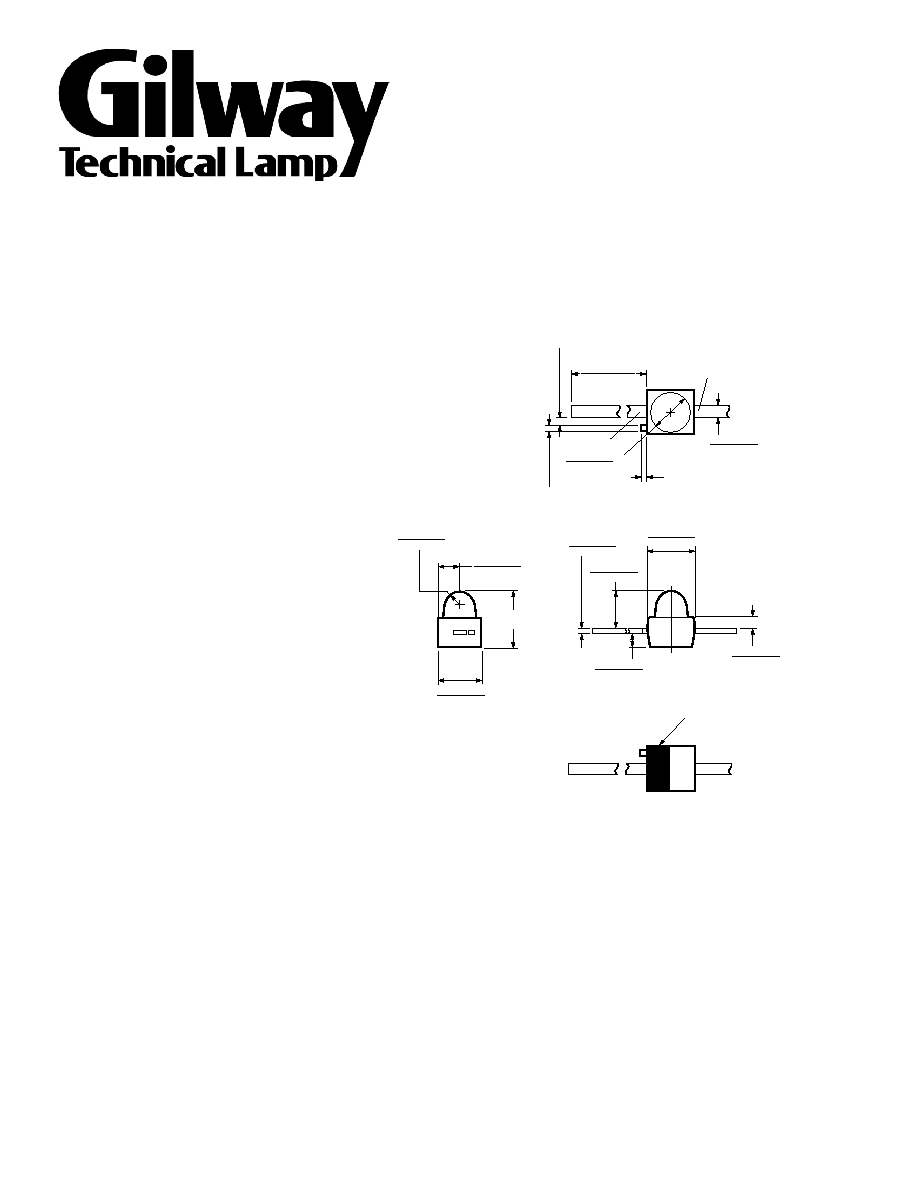
GHB-GW15-DR
0.50 (0.020) REF.
0.46(0.018)
0.56(0.022)
NOTE 3
ANODE
0.25 (0.010) MAX.*
NOTE 2
0.20 (0.008) MAX.
1.65(0.065)
1.91(0.075) DIA.
CATHODE
1
11
0..6
68
7((0
0..4
46
20
0))
BOTH SIDES
0.76(0.030) R.
0.89(0.035)
0.94 (0.037)
1.24 (0.049)
2.92 (0.115)
MAX.
2.08(0.082)
2.34(0.092)
2.03 (0.080)
1.78 (0.070)
(0.025)
0
0..6
33
8(0.015)
0.79 (0.031)
0.53 (0.021)
(0.007)
0
0..1
28
3(0.009)
(0.087)
2
1..2
91
6(0.077)
CATHODE STRIPE
NOTE 3
NOTES:
1. ALL DIMENSIONS ARE IN MILLIMETRES (INCHES).
2. PROTRUDING SUPPORT TAB IS CONNECTED TO ANODE LEAD.
3. LEAD POLARITY FOR THESE TS AlGaAs SUBMINIATURE LAMPS IS OPPOSITE TO THE
LEAD POLARITY OF SUBMINIATURE LAMPS USING OTHER LED TECHNOLOGIES.
Absolute Maximum Ratings at T
= 25
°
C
A
[2]
Peak Forward Current
.......................................................... 300 mA
[1,2]
Average Forward Current (@ I
= 300 mA)
PEAK
.................... 30 mA
[3]
DC Forward Current
............................................................... 50 mA
Power Dissipation .................................................................... 100 mW
Reverse Voltage (I
R
= 100 mA) ......................................................... 5 V
[4]
Transient Forward Current (10 m s Pulse)
............................ 500 mA
LED Junction Temperature ....................................................... 110
°C
Lead Soldering Temperature
[1.6 mm (0.063 in.) from body ............................ 260
°C for 5 seconds
Reflow Soldering Temperatures
Convective IR ..................... 235 °C Peak, above 183
°C for 90 seconds
Vapor Phase
........................................................ 215
°C for 3 minutes
Notes:
1. Maximum I
AVG
at f = 1 kHz, DF = 10%.
2. Refer to Figure 7 to establish pulsed operating conditions.
3. Derate linearly as shown in Figure 6.
4. The transient peak current is the maximum non-recurring peak current the device
can withstand without damaging the LED die and wire bonds. It is not
recommended that the device be operated at peak currents above the Absolute
Maximum Peak Forward Current.
Viewing Angle
Deep Red
Typical Iv
Typical Iv
Package Description
2q
1/2
R
d
= 644 nm
I
f
= 500
m
a
I
f
= 20 mA
Domed, Nondiffused
15
400
Untinted, Standard Current
Electrical Characteristics at T
A
= 25
°
C
Forward
Reverse
Capacitance
Speed of Response
Voltage
Breakdown
C
(pF)
t
s
(ns)
Part
V
F
(Volts)
V
R
(Volts)
V
F
= 0,
Thermal
Time Constant
Number
@ I
F
= 20 mA
@ I
R
= 100
m
A
f = 1 M Hz
Resistance
e
-t/t
HLMP-
Typ. Max.
Min.
Typ.
Typ.
R q
J-PIN
(
°
C/W)
Typ.
GHB-GW15-DR
1.9
2.4
5 20
20
170
45
s
h
V
Ð
R
E
L
A
T
I
V
E
E
F
F
I
C
I
E
N
C
Y
(
N
O
R
M
A
L
I
Z
E
D
A
T
2
0
m
A
)
0.0
5
300
I
PEAK
10
20
50
100
Ð PEAK FORWARD CURRENT Ð mA
1
2
1.2
1.1
1.0
0.9
0.8
0.7
0.6
0.5
0.4
0.3
0.2
0.1
200
R
E
L
A
T
I
V
E
I
N
T
E
N
S
I
T
Y
10
600
1000
-3
500
700
WAVELENGTH Ð nm
10
-2
10
-1
1.0
R
E
L
A
T
I
V
E
L
U
M
I
N
O
U
S
I
N
T
E
N
S
I
T
Y
(
N
O
R
M
A
L
I
Z
E
D
A
T
2
0
m
A
)
0.5
0.01
2
I
F
Ð DC FORWARD CURRENT Ð mA
5
10
20
50
2.4
2.0
1.0
0.2
0.1
0.05
0.5
1
I
F
Ð
F
O
R
W
A
R
D
C
U
R
R
E
N
T
Ð
m
A
300
20
1
1.0
3.5
V
F
1.5
2.0
2.5
3.0
Ð FORWARD VOLTAGE Ð V
200
100
50
10
5
2
0
0.5
I
A
V
G
=
A
V
E
R
A
G
E
F
O
R
W
A
R
D
C
U
R
R
E
N
T
Ð
m
A
0
50
I
PEAK
50
40
30
20
10
100
150
200
250
300
Ð PEAK FORWARD CURRENT Ð mA
f > 1000 Hz
f > 300 Hz
f > 100 Hz
I
F
Ð
F
O
R
W
A
R
D
C
U
R
R
E
N
T
Ð
m
A
0
0
T
A
50
40
30
20
10
20
40
60
80
100
Ð AMBIENT TEMPERATURE Ð ¡C
Rq
JA
= 400¡ C/W
Rq
JA
= 550¡ C/W
Notes:
1. The luminous intensity, Iv, is measured at the mechanical axis of the lamp package. The actual peak of the spatial radiation pattern
may not be aligned with this axis.
2. f
v
is the total luminous flux output as measured with an integrating sphere.
3. The dominant wavelength,
l
d
, is derived from the CIE Chromaticity Diagram and represents the color of the device.
4. q
1
/
2
is the off-axis angle w here the luminous intensity is 1/2 the peak intensity.
5. Radiant intensity, I
v
, in watts/steradian, may be calculated from the equation I
v
= I
v
/h
v
, where I
v
is the luminous intensity in candelas
and h
v
is the luminous efficacy in lumens/watt.
Optical Characteristics at T
A
= 25
°
C
Luminous
Color,
Viewing
Intensity
Total Flux
Peak
Dominant
Angle
Luminous
Part
I
V
(mcd)
f
V
1
(mlm)
Wavelength
Wavelength
2 q /
2
Efficacy
@ 20 mA
[1]
@ 20 mA
[2]
l
peak
(nm)
l
[3]
d
(nm)
Degrees
[4]
h
v
[5]
Min.
Typ.
Typ.
Typ.
Typ.
Typ.
(lm/w)
GHB-GW15-DR
100
400
280
654
644
15
85
N
O
R
M
A
L
I
Z
E
D
I
N
T
E
N
S
I
T
Y
1.0
0.8
0.7
0.6
0.5
0.4
0.3
0.2
0.1
0
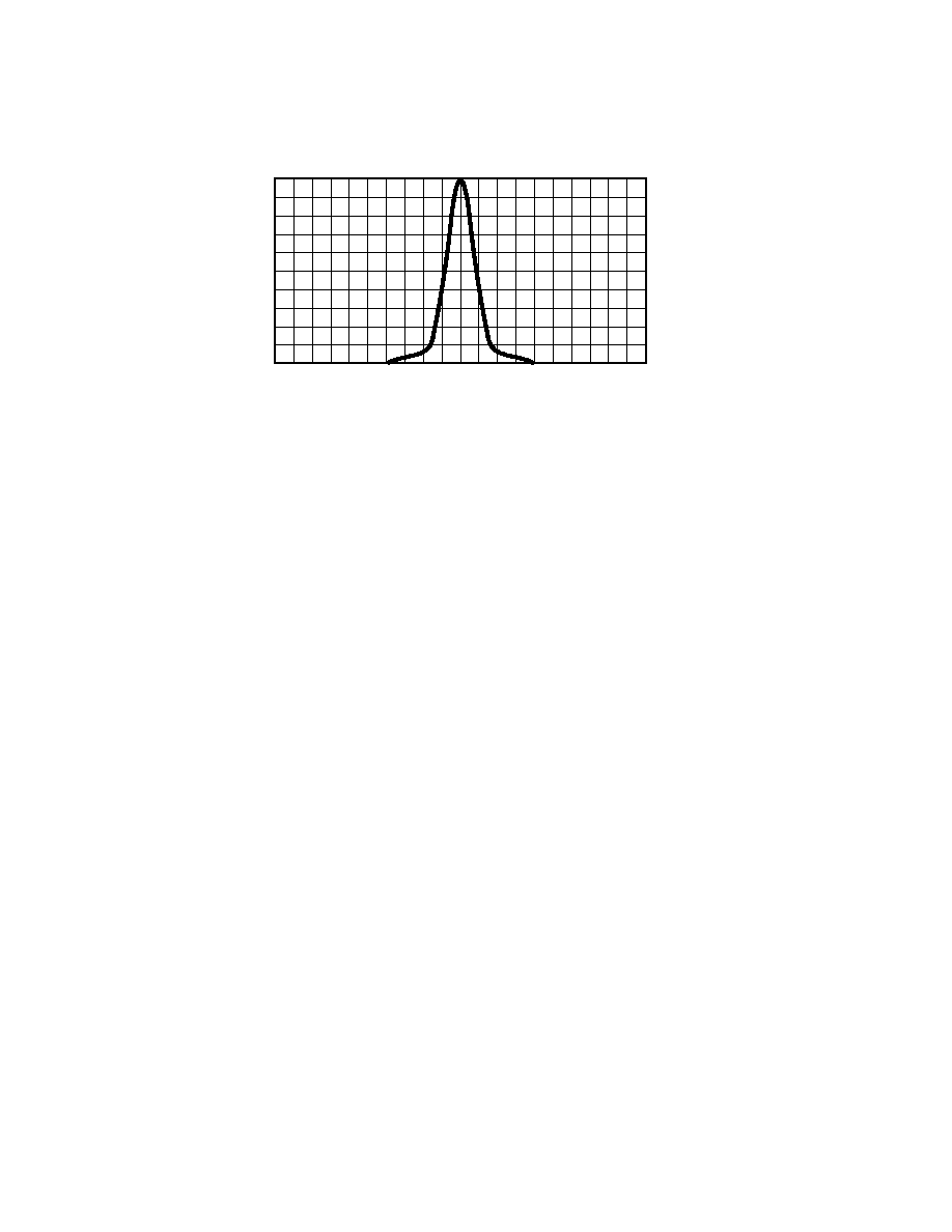
100¡ 90¡
ANGULAR DISPLACEMENT Ð DEGREES
0.9
80¡ 70¡ 60¡ 50¡ 40¡ 30¡ 20¡ 10¡ 0¡
10¡ 20¡ 30¡ 40¡ 50¡ 60¡ 70¡ 80¡ 90¡ 100¡
Document Outline