
G -LINK
GLT4160L04
4M X 4 CMOS DYNAMIC RAM WITH EXTENDED DATA OUTPUT
Apr 2003 (Rev.4.1)
G-Link Technology Corporation,Taiwan
Web : www.glink.com.tw Email : sales@glink.com.tw
TEL : 886-2-26599658
- 1 -
Features :
Description :
4,194,304 words by 4 bits organization.
Fast access time and cycle time
Low power dissipation.
Read-Modify-Write,
RAS
-Only Refresh,
CAS
-Before-
RAS
Refresh, Hidden Refresh.
2,048 refresh cycles per 32ms.
Available in 300 mil 26(24) SOJ and TSOPII.
3.3V
±
0.3V Vcc Power Supply voltage
.
All inputs and Outputs are LVTTL compatible.
Extended Data-Out (EDO) Page access
cycle.
Self-refresh Capability
. (S-Version).
The GLT4160L04 is a high-performance
CMOS dynamic random access memory
containing 16,777,216 bits organized in a x4
configuration. The GLT4160L04 offers page
cycle access with Extended Data Output.
The GLT4160L04 has 11 row- and 11
column-addresses, and accepts 2048-cycle
refresh in 32 ms.
The GLT4160L04 provides EDO PAGE
MODE operation which allows for fast data
access within a row-address defined
boundary, up to 2048 x 4 bits with cycle
times as short as 18ns.
HIGH PERFORMANCE
40
45
50
60
70
Max.
RAS
Access Time, (t
RAC
)
40 ns
45 ns
50 ns
60 ns
70 ns
Max. Column Address Access Time, (t
AA
)
20 ns
22 ns
25 ns
30 ns
35 ns
Min. Extended Data Out Page Mode Cycle Time, (t
PC
)
18 ns
18 ns
20 ns
25 ns
30 ns
Min. Read/Write Cycle Time, (t
RC
)
70 ns
80 ns
84 ns
104 ns 124 ns
Max.
CAS
Access Time (t
CAC
)
12 ns
12 ns
13 ns
15 ns
20 ns
G -LINK
GLT4160L04
4M X 4 CMOS DYNAMIC RAM WITH EXTENDED DATA OUTPUT
Apr 2003 (Rev.4.1)
G-Link Technology Corporation,Taiwan
Web : www.glink.com.tw Email : sales@glink.com.tw
TEL : 886-2-26599658
- 2 -
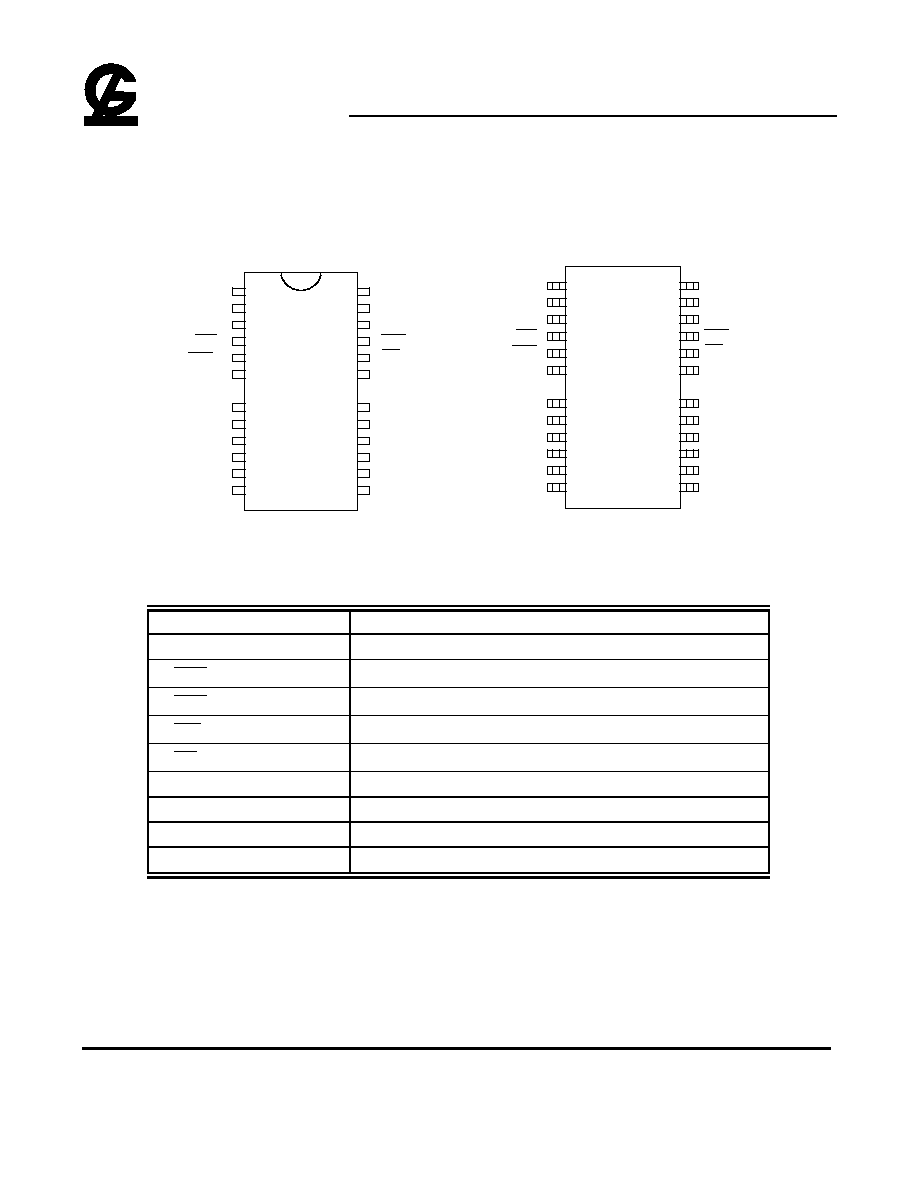
Pin Configuration :
V
cc
DQ
0
A
0
A
1
A
2
A
3
1
2
3
4
5
6
8
9
10
11
12
13
22
21
19
18
17
16
15
14
26
25
24
23
A
9
A
8
A
7
A
6
OE
CAS
V
SS
DQ
3
DQ
1
WE
RAS
NC
V
CC
DQ
2
A
5
A
4
V
SS
A
10
V
cc
DQ
0
A
10
A
0
A
1
A
2
A
3
1
2
3
4
5
6
8
9
10
11
12
13
22
21
19
18
17
16
15
14
26
25
24
23
A
9
A
8
A
7
A
6
OE
CAS
V
SS
DQ
3
DQ
1
WE
RAS
NC
V
CC
DQ
2
A
5
A
4
V
SS
Pin Descriptions:
Name
Function
A
0
- A
10
Address Inputs
RAS
Row Address Strobe
CAS
Column Address Strobe
WE
Write Enable
OE
Output Enable
DQ
0
- DQ
3
Data Inputs / Outputs
V
CC
+3.3V Power Supply
V
SS
Ground
NC
No Connection
GLT4160L04
300mil 26(24) TSOPII
GLT4160L04
300mil 26(24) SOJ

G -LINK
GLT4160L04
4M X 4 CMOS DYNAMIC RAM WITH EXTENDED DATA OUTPUT
Apr 2003 (Rev.4.1)
G-Link Technology Corporation,Taiwan
Web : www.glink.com.tw Email : sales@glink.com.tw
TEL : 886-2-26599658
- 3 -
Absolute Maximum Ratings*
Capacitance*
T
A
=25
∞
C, V
CC
=3.3V
±
0.3V, V
SS
=0V
Operating Temperature, T
A
(ambient)
.................................................0
∞
C to
+70
∞
C
For Extended Temperature.................-20
∞
C to 85
∞
C
Storage Temperature(plastic)............-55
∞
C to +150
∞
C
Voltage Relative to V
SS
........................-0.5V to + 4.6V
Short Circuit Output Current...............................20mA
Power Dissipation...............................................1.0W
Symbol
C
IN1
C
IN2
C
OUT
Parameter
Address Input
RAS, CAS, WE, OE
Data Input/Output
Max.
5
7
7
Unit
pF
pF
pF
*Note: Operation above Absolute Maximum Ratings can
aversely affect device reliability.
*Note: Capacitance is sampled and not 100% tested
Electrical Specifications
l
All voltages are referenced to GND.
l
After power up, wait more than 200
µ
s and then, execute eight
CAS
-before-
RAS
or
RAS
-only
refresh cycles as dummy cycles to initialize internal circuit.
Block Diagram :
NO.2 CLOCK
GENERATOR
COLUMN-
ADDRESS
BUFFER(11)
REFRESH
CONTROLLER
REFRESH
COUNTER
ROW
ADDRESS
BUFFERS(11)
NO.1 CLOCK
GENERATOR
11
11
A
1
A
2
A
3
A
4
A
5
A
6
A
7
A
8
A
9
A
10
RAS
11
11
COLUMN
DECODER
DATA-OUT
BUFFER
DATA-IN
BUFFER
SENSE AMPLIFIERS
I/O GATING
2048 x 1024 x 4
MEMORY
ARRAY
2048
2048
4
4
4
4
WE
CAS
DQ
0
DQ
1
DQ
2
DQ
3
OE
V
DD
V
SS
ROW DECODER
2048
A
0

G -LINK
GLT4160L04
4M X 4 CMOS DYNAMIC RAM WITH EXTENDED DATA OUTPUT
Apr 2003 (Rev.4.1)
G-Link Technology Corporation,Taiwan
Web : www.glink.com.tw Email : sales@glink.com.tw
TEL : 886-2-26599658
- 4 -
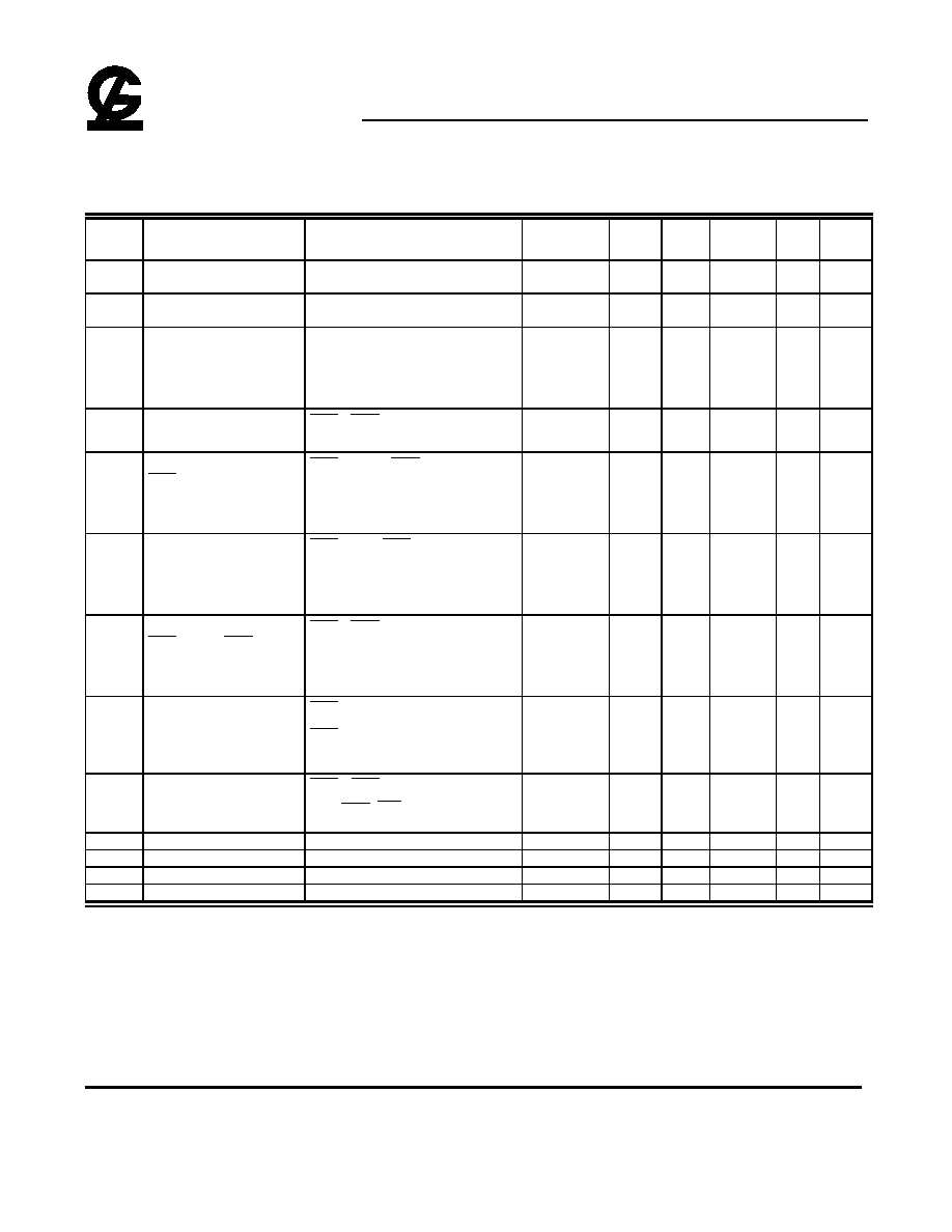
Truth Table:
Function
RAS
CAS
WE
OE
ADDRESS
DATA-IN/OUT
t
R
t
C
DQ1-DQ4
Standby
H
H
X
X
X
X
X
High-Z
READ
L
L
H
L
ROW
COL
Data-Out
EARLY WRITE
L
L
L
X
ROW
COL
Data-In
READ WRITE
L
L
H
L
L
H
ROW
COL
Data-Out,Data-In
EDO-PAGE-MODE
1st Cycle
L
H
L
H
L
ROW
COL
Data-Out
READ
2nd cycle
L
H
L
H
L
n/a
COL
Data-Out
EDO-PAGE-MODE
1st Cycle
L
H
L
L
X
ROW
COL
Data-In
EARLY-WRITE
2nd cycle
L
H
L
L
X
n/a
COL
Data-In
EDO-PAGE-MODE
1st Cycle
L
H
L
H
L
L
H
ROW
COL
Data-Out,Data-In
READ-WRITE
2nd cycle
L
H
L
H
L
L
H
n/a
COL
Data-Out,Data-In
RAS
-ONLY REFRESH
L
H
X
X
ROW
n/a
High-Z
HIDDEN REFRESH
READ
L
H
L
L
H
L
ROW
COL
Data-Out
WRITE
L
H
L
L
L
X
ROW
COL
Data-In
CBR REFRESH
H
L
L
H
X
X
X
High-Z
SELF REFRESH
H
L
L
H
X
X
X
High-Z
G -LINK
GLT4160L04
4M X 4 CMOS DYNAMIC RAM WITH EXTENDED DATA OUTPUT
Apr 2003 (Rev.4.1)
G-Link Technology Corporation,Taiwan
Web : www.glink.com.tw Email : sales@glink.com.tw
TEL : 886-2-26599658
- 5 -
DC and Operating Characteristics (1-2)
T
A
= 0
∞
C to 70
∞
C, -20
∞
C to 85
∞
C V
CC
=3.3V
±
0.3V, V
SS
=0V, unless otherwise specified.
Sym.
Parameter
Test Conditions
Access
Time
Min.
Typ
Max.
Unit Notes
I
LI
Input Leakage Current
(any input pin)
0V
V
IN
V
CC
+0.3V
(All other pins not under test=0V)
-5
+5
µ
A
I
LO
Output Leakage Current
(for High-Z State)
0V
V
out
V
CC
Output is disabled (Hiz)
-5
+5
µ
A
I
CC1
Operating Current,
Random READ/WRITE
t
RC
= t
RC
(min.)
t
RAC
= 40ns
t
RAC
= 45ns
t
RAC
= 50ns
t
RAC
= 60ns
t
RAC
= 70ns
130
120
80
70
mA
1,2
I
CC2
Standby Current (TTL)
RAS
,
CAS
at V
IH
other inputs
V
SS
1
mA
I
CC3
Refresh Current,
RAS
-Only
RAS
cycling,
CAS
at V
IH
t
RC
= t
RC
(min.)
t
RAC
= 40ns
t
RAC
= 45ns
t
RAC
= 50ns
t
RAC
= 60ns
t
RAC
= 70ns
130
120
80
70
mA
2
I
CC4
Operating Current,
EDO Page Mode
RAS
at V
IL
,
CAS
address
cycling:t
PC
=t
PC
(min.)
t
RAC
= 40ns
t
RAC
= 45ns
t
RAC
= 50ns
t
RAC
= 60ns
t
RAC
= 70ns
130
120
80
70
mA
1,2
I
CC5
Refresh Current,
CAS
Before
RAS
RAS
,
CAS
address cycling: t
RC
=t
RC
(min.)
t
RAC
= 40ns
t
RAC
= 45ns
t
RAC
= 50ns
t
RAC
= 60ns
t
RAC
= 70ns
130
120
80
70
mA
2
I
CC6
Standby Current, (CMOS)
RAS
V
CC
-0.2V,
CAS
V
CC
-0.2V,
All other inputs V
SS
300
µ
A
1,5
I
CC7
Self refresh Current
RAS
=
CAS
=0.2V,
WE = OE = A
0
~A
10
=V
CC
-0.2V or 0.2V
DQ
0
~DQ
3
=V
CC
-0.2V,0.2V or Open
300
µ
A
V
IL
Input Low Voltage
-0.3
+0.8
V
3
V
IH
Input High Voltage
2.0
V
CC
+0.3
V
4
V
OL
Output Low Voltage
I
OL
= 2mA
0.4
V
V
OH
Output High Voltage
I
OH
= -2mA
2.4
V
Notes:
1. I
CC
is dependent on output loading when the device output is selected. Specified I
CC
(max.) is measured with the output open.
2. I
CC
is dependent upon the number of address transitions specified ICC(max.) is measured with a maximum of one transition per address cycle
in random Read/Write and EDO Fast Page Mode.
3. Specified V
IL
(min.) is steady state operation. During transitions V
IL
(min.) may undershoot to ≠1V for a period not to exceed 15ns. All AC
parameters are measured with V
IL
(min.)
V
SS
and V
IH
(max.)
V
CC
.
4. Specified V
IH
(max.) is steady state operation . During transitions V
IH
(max.) may overshoot to V
CC
+1V for a period not to exceed 15ns. All AC
parameters are measured with V
IL
(min.)
V
SS
and VIH(max.)
V
CC
.
5. S-Version.