Features
40HF(R) SERIES
POWER RECTIFIER
Reverse Voltage -
100 to 1600 Volts
Forward Current -
40.0 Amperes
High surge current capability
Designed for a wide range of applications
Stud cathode and stud anode version
Leaded version available
Types up to 1600V V
RRM
Major Ratings and Characteristics
1
Typical Applications
Battery charges
Converters
Power supplies
Machine tool controls
Parameters
40HF(R)
Units
10 to 120
140 to 160
I
F(AV)
40
40
Amps
@T
C
140
110
I
F(RMS)
62
Amps
I
FSM
@50Hz
570
Amps
@60Hz
595
Amps
I
2
t
@50Hz
1600
A
2
s
@60Hz
1450
A
2
s
V
RRM
range
100 to 1200
1400 to 1600
Volts
T
J
range
-65 to 190
-65 to 160
Mechanical Data
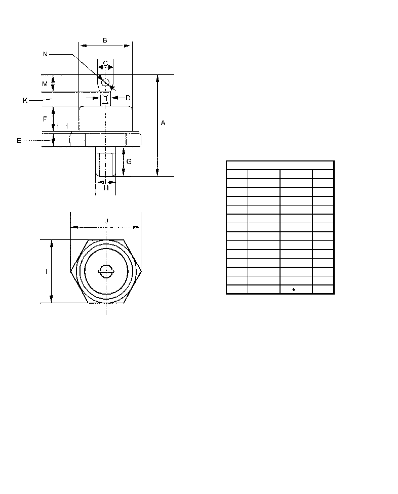
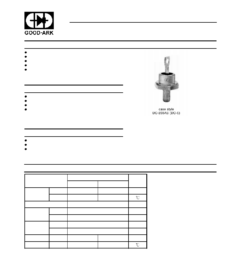
Case: DO-203AB(DO-5)
Polarity: Selection available
Weight: 17 grams
2
ELECTRICAL SPECIFICATIONS
Type
number
Voltage
Code
V
RRM
maximum
repetitive peak
reverse voltage
Volts
V
RSM
maximum
non-repetitive peak
reverse voltage
Volts
V
R(BR)
minimum
avalanche voltage
Volts
(1)
I
RRM
max.
@T
J
=T
J
max.
mA
40HF(R)
10
100
200
-
15
20
200
300
-
40
400
500
500
60
600
720
725
9
80
800
960
950
100
1000
1200
1150
120
1200
1440
1350
140
1400
1650
1550
4.5
160
1600
1900
1750
(1) Avalanche version only available from V
RRM
400V to 1600V.
Parameter
40HF(R)
Units Conditions
10 to 120
140 to 160
I
F(AV)
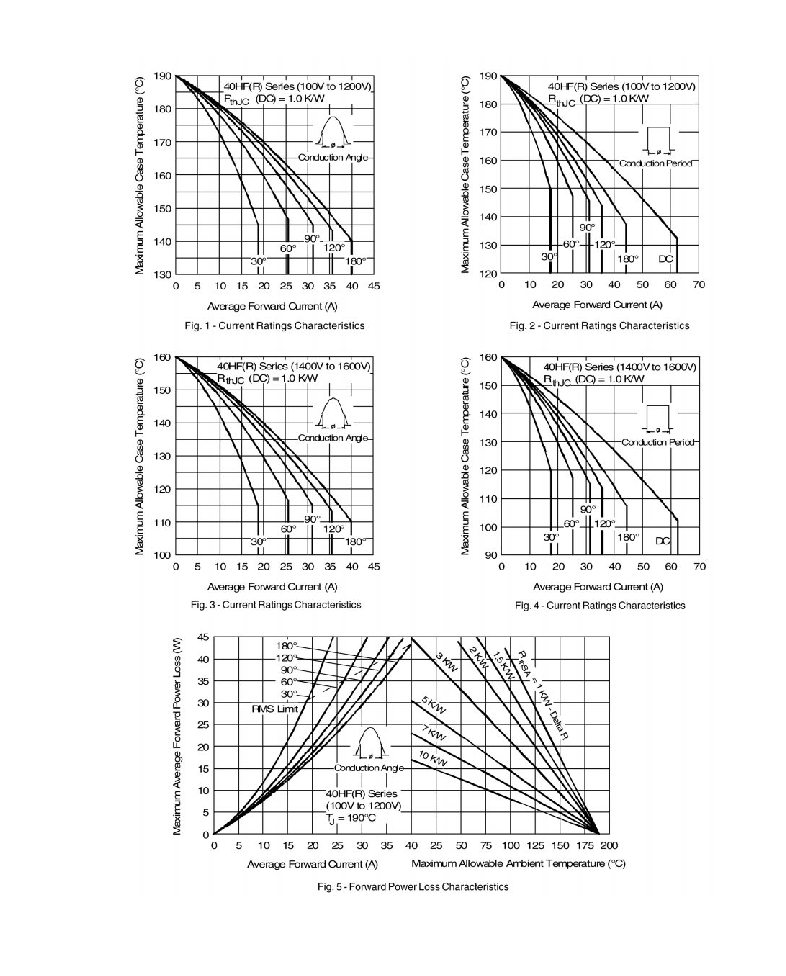
Max. average forward current
@ Case temperature
40
40
Amps
180
O
conduction, half sine wave
140
110
I
F(RMS)
Max. RMS forward current
62
Amps
I
FSM
Max. peak, one-cycle forward,
non-repetitive surge current
570
Amps
t=10ms
No voltage
reapplied
Sinusoidal half wave
Initial T
J
=T
J
max.
595
t=8.3ms
480
t=10ms
100% V
RRM
reapplied
500
t=8.3ms
I
2
t
Maximum I
2
t for fusing
1600
A
2
S
t=10ms
No voltage
reapplied
1450
t=8.3s
1150
t=10ms
100% V
RRM
reapplied
1050
t=8.3ms
V
FM
Max. forward voltage drop
1.30
Volts
I
pk
=125A, T
J
=25 , t
p
=400us rectangular wave
Forward Conduction
Voltage Ratings
3
Parameter
40HF(R)
Units Conditions
10 to 120
140 to 160
T
J
Max. junction operating temperature range
-65 to 190
-65 to 160
T
stg
Max. storage temperature range
-65 to 190
-65 to 160
R
thJC
Max. thermal resistance, junction to case
1.0
K/W
DC operation
R
thCS
Max. thermal resistance, case to heatsink
0.25
Mounting surface, smooth, flat and
greased
T Max. allowed mounting torque 10%
2.3-2.4
Nm
Not lubricated threads
20-30
lbf-in
wt approximate weight
17 (0.6)
g(oz)
Case style
DO-203AB (DO-5)
See Outline Table
Thermal and Mechanical Specifications
Ordering information Table
Device Code:
40
HF
R
160 M
1
2
3
4
5
1. 40 - Standard device
2. HF - Standard diode
3. None - stud normal polarity (cathode to stud)
R - stud reverse polarity (Anode to stud)
4. Voltage code: cade x 10=V
RRM
5. None - stud base DO-203AB (DO-5) 1/4 28 UNF-2A
M - stud base DO-203AB (DO-5) M6x1


