Notes:
(1) Measured at 1.0MHz and applied reverse voltage of 4.0 VDC
(2) Thermal resistance junction to ambient and from junction to lead at 0.375 (9.5mm) lead length, P.C.B. mounted
Symbols
BY127
BY133
EM513
EM516
Units
Maximum repetitive peak reverse voltage
V
RRM
1250
1300
1600
1800
Volts
Maximum RMS voltage
V
RMS
875
910
1120
1270
Volts
Maximum DC blocking voltage
V
DC
1250
1300
1600
1800
Volts
Maximum average forward rectified current
0.375" (9.5mm) lead length at T
A
=75
I
(AV)
1.0
Amp
Peak forward surge current
8.3mS single half sine-wave superimposed
on rated load (MIL-STD-750D 4066 method)
I
FSM
30.0
Amps
Maximum forward voltage at 1.0A DC and 25
V
F
1.1
Volts
Maximum full load reverse current T
A
=25
at rated DC blocking voltage T
A
=100
I
R
5.0
200.0
A
Typical junction capacitance (Note 1)
C
J
15.0
F
Typical thermal resistance (Note 2)
R
JA
R
JL
50.0
25.0
/W
Operating and storage temperature range
T
J
, T
STG
-55 to +150
Features
BY127, BY133, EM513, EM516
GENERAL PURPOSE PLASTIC RECTIFIER
Reverse Voltage -
1250 to 1800 Volts
Forward Current -
1.0 Ampere
The plastic package carries Underwriters Laboratory
Flammability Classification 94V-0
Construction utilizes void-free molded plastic technique
Low reverse leakage
Low forward voltage drop
High current capability
High reliability
High surge current capability
Maximum Ratings and Electrical Characteristics
1
Ratings at 25 ambient temperature unless otherwise specified.
Single phase, half wave, 60Hz, resistive or inductive load.
For capacitive load, derate current by 20%.
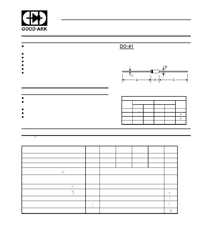
Mechanical Data
Case: Molded plastic, DO-41
Lead: Axial leads, solderable per MIL-STD-202,
method 208 guaranteed
Polarity: Color band denotes cathode end
Mounting Position: Any
Weight: 0.012 ounce, 0.33 gram
DIMENSIONS
DIM
inches
mm
Note
Min.
Max.
Min.
Max.
A
0.165
0.205
4.2
5.2
B
0.079
0.106
2.0
2.7
C
0.028
0.034
0.71
0.86
D
1.000
-
25.40
-
