Notes:
(1) Reverse recovery test conditions: I
F
=0.5A, I
R
=1.0A, I
rr
=0.25A
(2) Measured at 1.0MHz and applied reverse voltage of 4.0 volts
(3) Pulse test: pulse width 300uSec, Duty cycle 2%
Symbols
RL101F RL102F RL103F RL104F RL105F RL106F RL107F
Units
Maximum repetitive peak reverse voltage
V
RRM
50
100
200
400
600
800
1000
Volts
Maximum RMS voltage
V
RMS
35
70
140
280
420
560
700
Volts
Maximum DC blocking voltage
V
DC
50
100
200
400
600
800
1000
Volts
Average forward current
at T
A
=55
I
(AV)
1.0
Amp
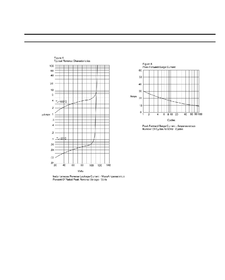
Peak forward surge current
8.3mS single half sine-wave
I
FSM
30.0
Amps
Maximum instantaneous forward voltage
at I
FM
=1.0A; T
J
=25 (Note 3)
V
F
1.30
Volts
Maximum DC reverse current T
J
=25
at rated DC blocking voltage T
J
=100
I
R
5.0
100.0
A
Maximum reverse recovery time (Note 1)
T
rr
150
250
500
nS
Typical junction capacitance (Note 2)
C
J
15.0
F
Maximum thermal resistance
R
JL
50
/W
Operating and storage temperature range
T
J
, T
STG
-65 to +175
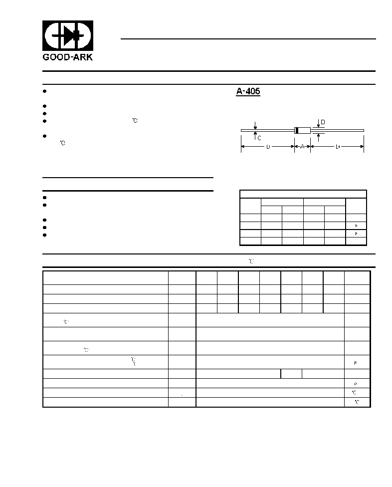
Features
RL101F THRU RL107F
FAST SWITCHING PLASITC RECTIFIER
Reverse Voltage -
50 to 1000 Volts
Forward Current -
1.0 Ampere
Maximum Ratings and Electrical Characteristics
@25 unless otherwise specified
1
Maximum Ratings
DIMENSIONS
DIM
inches
mm
Note
Min.
Max.
Min.
Max.
A
0.165
0.205
4.2
5.2
B
0.079
0.106
2.0
2.7
C
0.020
0.024
0.5
0.6
D
1.000
-
25.40
-
Plastic package has Underwriters Laboratory
Flammability Classification 94V-0
Fast switching for high efficiency
Construction utilizes void-free molded plastic technique
1.0 ampere operation at T
A
=55 with no thermal
runaway
High temperature soldering guaranteed:
250 /10 seconds, 0.375(9.5mm) lead length,
5 lbs. (2.3kg) tension
Case: A-405 molded plastic body
Terminals: Plated axial leads, solderable per
MIL-STD-750, method 2026
Polarity: Color band denotes cathode end
Mounting Position: Any
Weight: 0.008 ounce, 0.23 gram