
High Speed Response (Rise Time = 0.7ns, TTS = 0.16ns FWHM)
25mm (1 Inch) Diameter, 10 - stage, Multialkali Photocathode, Head - On Type
Dynode
Photocathode
Wavelength of Maximum Response
Material
Minimum Effective Area
Structure
Number of Stages
Case
300 to 850
420
Borosilicate glass
Linear focused
Magnetic shield case
nm
nm
mm dia.
--
--
--
--
--
GENERAL
MAXIMUM RATINGS (Absolute Maximum Values)
∞
C
-2500
-30 to +50
0.016
Vdc
mA
Supply Voltage
Average Anode Current
Ambient Temperature
Between Anode and Cathode
CHARACTERISTICS (at 25
∞
C)
Radiant at 420 nm
Transit Time Spread (FWHM)
Anode
Sensitivity
Gain
Anode Pulse Rise Time
Electron Transit Time
Time
Response
--
--
1.3
◊
10
6
--
--
--
--
A/lm
Cathode
Sensitivity
Luminous (2856 K)
--
80
120
51
150
Luminous (2856 K)
100
ns
Parameter
Description/Value
Unit
Spectral Response
Window Material
Multialkali
20
10
Parameter
Unit
Description/Value
Parameter
Unit
Max.
Typ.
Min.
µ
A/lm
mA/W
--
VOLTAGE DISTRIBUTION RATIO AND SUPPLY VOLTAGE
Electrode
K
G
Dy1
Dy3
Dy4
Dy2
Dy5
Dy6
Dy7
Dy8
P
Supply Voltage: -2250 Vdc, K: Cathode, Dy: Dynode, P: Anode, G: Grid
Acc to be connected to Dy7
1
1
1.5
1
1
1
1.8
1.2
4.8
1.3
Ratio
PHOTOMULTIPLIER TUBE
ASSEMBLY
H7313
--
--
0.7
--
400
nA
3
2.5
Dy9
Dy10
Anode Dark Current (after 30 min. storage in darkness)
ns
--
--
0.16
--
10
--
ns
NOTE: Anode characteristics are measured with a voltage distribution ratio shown below.
Information furnished by HAMAMATSU is believed to be reliable. However, no responsibility is assumed for possible inaccuracies or omissions.
Specifications are subjected to change without notice. No patent right are granted to any of the circuits described herein.
c
1998 Hamamatsu Photonics K.K.
Subject to local technical requirements and regulations, availability of products included in this promotional material may vary. Please consult with our sales office.
--
R5322
Assembled Photomultiplier Tube
Voltage Divider Current
0.36
mA
PHOTOMULTIPLIER TUBE ASSEMBLY H7313
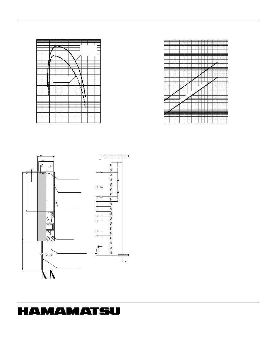
Figure 1: Typical Spectral Response
Figure 3: Dimensional Outline and Circuit Diagram (Unit: mm)
TPMHA0418EA
TPMHB0401EB
TPMH1200E01
FEB. 1998 SI
Printed in Japan (500)
HAMAMATSU PHOTONICS K.K., Electron Tube Center
314-5, Shimokanzo, Toyooka-village, Iwata-gun, Shizuoka-ken, 438-0193 Japan, Telephone:(81)539/62-5248, Fax:(81)539/62-2205
U.S.A.: Hamamatsu Corporation: 360 Foothill Road, P.O.Box 6910, Bridgewater, N.J. 08807-0910, U.S.A., Telephone:(1)908-231-0960, Fax:(1)908-231-1218
Germany: Hamamatsu Photonics Deutschland GmbH: Arzbergerstr. 10, D-82211 Herrsching am Ammersee, Germany, Telephone:(49)8152-375-0, Fax:(49)8152-2658
France: Hamamatsu Photonics France: S.A.R.L.: 8, Rue du Saule Trapu, Parc du Moulin de Massy, 91882 Massy Cedex, France, Telephone:(33)1 69 53 71 00, Fax:(33)1 69 53 71 10
United Kingdom: Hamamatsu Photonics UK Limited: Lough Point, 2 Gladbeck Way, Windmill Hill, Enfield, Middlesex EN2 7JA, United Kingdom, Telephone:(44)181-367-3560, Fax:(44)181-367-6384
North Europe: Hamamatsu Photonics Norden AB: F‰rˆgatan 7, S-164 40 Kista, Sweden, Telephone:(46)8-703-29-50, Fax:(46)8-750-58-95
Italy: Hamamatsu Photonics Italia S.R.L.: Via della Moia, 1/E 20020 Arese, (Milano), Italy ,Telephone: (39)2 935 81 733 Fax: (39)2 935 81 741
31.0
±
0.5
26
±
1
20MIN.
120.0
±
0.8
71
±
1
1500
1MAX.
PHOTOCATHODE
PMT: R5322
WITH HA COATING
MAGNETIC SHIELD
CASE (t = 0.8 mm)
POTTING
COMPOUND
SIGNAL OUTPUT
: RG-174/U (BLACK)
-H.V
: COAXIAL CABLE (RED)
R19
R18
R17
R16
R15
R14
R13
R12
R11
R10
R9
R8
R7
R6
R5
R4
R3
R2
R1
DY10
DY9
DY8
DY7
DY6
DY5
DY4
DY3
DY2
DY1
-H.V
: COAXIAL CABLE (RED)
P
C4
C3
C2
C1
K
SIGNAL OUTPUT
: RG-174/U (BLACK)
R1, R3, R19
R2, R7 to R12, R15 to R17
R4
R5, R18
R6, R14
R13
R20 to R22
C1 to C3
C4
: 430 k
: 330 k
: 820 k
: 390 k
: 270 k
: 220 k
: 51
: 0.022
µ
F
: 0.033
µ
F
R22
R21
R20
F
ACC
*
TO MAGNETIC
SHIELD CASE
* MAGNETIC SHIELD IS CONNECTED
TO GND INSIDE OF THIS PRODUCT.
CATHODE RADIANT SENSITIVITY (mA / W)
QUANTUM EFFICIENCY (%)
WAVELENGTH (nm)
200
400
600
800
1000
0.01
0.1
0
10
100
QUANTUM
EFFICIENCY
CATHODE
RADIANT
SENSITIVITY
SUPPLY VOLTAGE (V)
GAIN
ANODE DARK CURRENT (A)
1000
1500
2000
2500
3000
at 25
∞
C
ANODE DARK CURRENT
10
2
10
3
10
4
10
5
10
6
10
7
10
8
10
-10
10
-9
10
-8
10
-7
10
-6
10
-5
10
-4
GAIN
Figure 2: Typical Gain and Anode Dark Current
TPMHB0467EA