40
Product Variations
Specifications
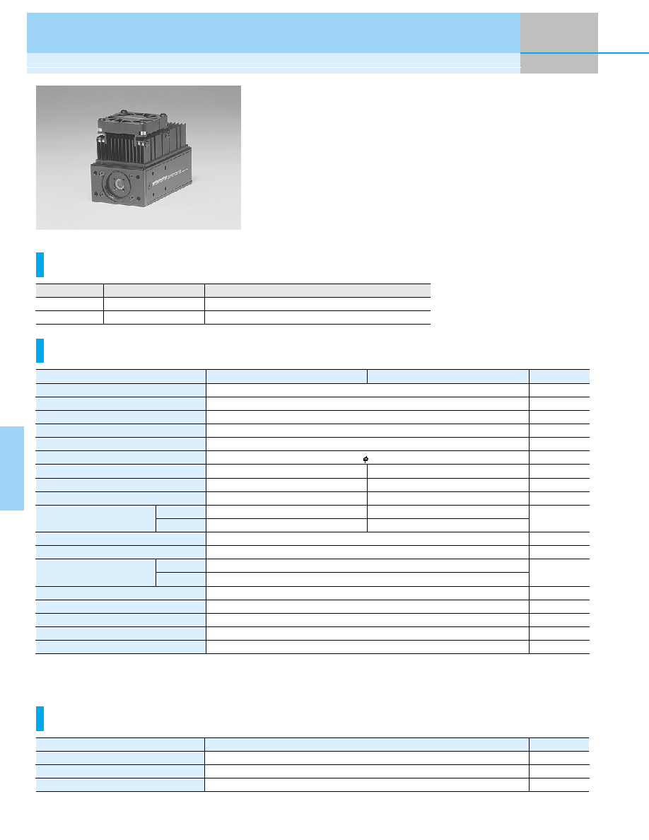
The H7421 series are photon counting head devices containing a metal
package photomultiplier tube having a GaAsP/GaAs photocathode and a
thermoelectric cooler. The thermoelectric cooler reduces thermal noise gen-
erated from the photocathode which also offers a high quantum efficiency, al-
lowing measurement to be made with a good S/N ratio even at very low light
levels.
The H7421-40 has high sensitivity on wavelength from 300 nm to 720 nm.
The H7421-50 is sensitive over a wide spectral range from 380 nm to 890 nm.
The photomultiplier tube is maintained at a constant temperature by monitor-
ing the output from a thermistor installed near the photomultiplier tube and
regulating the current to the thermoelectric cooler.
Metal package PMT with Cooler
Photon Counting Head H7421 Series
Cooling Specifications
Type No.
Parameter
H7421-40
H7421-50
Input Voltage
Max. Input Voltage for Main Unit
Max. Input Current for Main Unit
Max. Input Voltage for Thermoelectric Cooler
Max. Input Current for Thermoelectric Cooler
Effective Area
Peak Sensitivity Wavelength
Count Sensitivity
Count Linearity *
1
Dark Count *
2
*
3
Pulse-pair Resolution
Output Pulse Width
Output Pulse Height *
4
Recommended Load Resistance
Signal Output Logic
Operating Ambient Temperature
Storage Temperature
Weight
+4.5 to +5.5
+6
50
2.6
2.2
5
70
30
3.6
3.0
50
Positive logic
+5 to +35
-20 to +50
340
H7421-40
580
7.8
◊ 10
5
1.5
◊ 10
6
100
300
H7421-50
800
3.9
◊ 10
5
1.5
◊ 10
6
125
375
Unit
V
V
mA
V
A
mm
nm
s
-1
∑pW
-1
s
-1
s
-1
ns
ns
V
--
∞C
∞C
g
Typ.
Max.
Typ.
Min.
300 nm to 720 nm
380 nm to 890 nm
Spectral Response
GaAsP photocathode, QE 40 % at peak wavelength
GaAs photocathode, QE 12 % at peak wavelength
Features
*1: Random pulse, at 10 % count loss
*2: PMT setting temperature 0
∞C, used with C8137, M9011 and A7432
*3: After 30 minute storage in darkness
*4: With input voltage +5 V, Load resistance 50
and Coaxial cable RG-174/U (450 mm)
*5: Input current to thermoelectric cooler = 2.0 A
Parameter
Cooling Method
Max. Cooling Temperature (
T) *
5
Cooling Time *
5
Thermoelectric cooling
35
Approx. 5
--
∞C
min
H7421-40/H7421-50
Unit
Heatsink with fan (A7423) sold separately
41
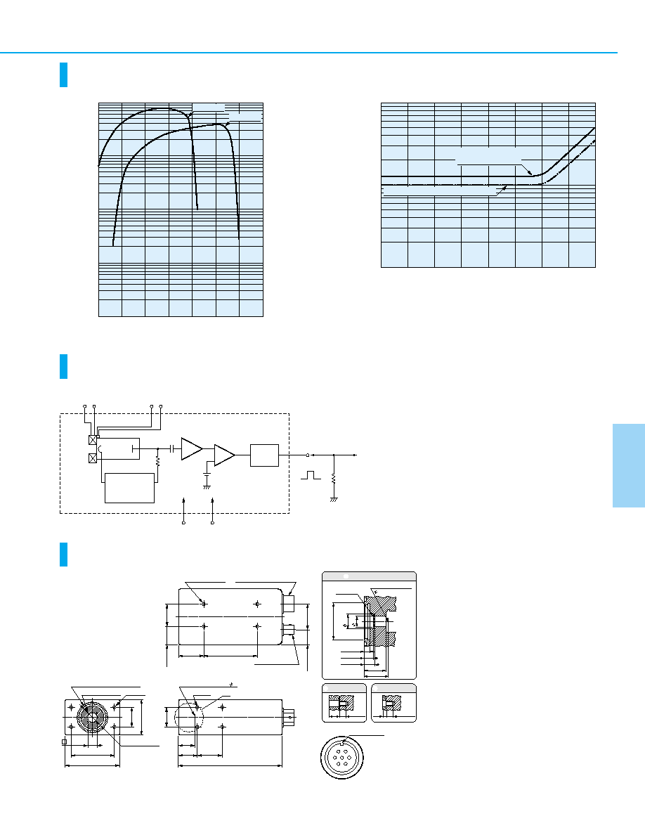
Characteristics
(Count sensitivity, Dark count)
Block Diagram
Dimensional Outlines
(Unit: mm)
TPHOB0042ED
TPHOB0046EB
TPHOC0042ED
TPHOA0021EC
10
6
10
5
10
4
10
3
10
2
300
400
500
600
WAVELENGTH (nm)
COUNT SENSITIVITY (s
-1
∑
pW
-1
)
700
800
900
1000
H7421-50
H7421-40
5
10
10
100
1000
15
20
25
AMBIENT TEMPERATURE (
∞C)
D
ARK COUNT (s
-1
)
30
35
40
45
H7421-50 (when used
with C8137, A7423)
H7421-40 (when used wih C8137, A7423)
Photon Counting Heads
F
A
D
E
B
C
G
7.2
10.2
M25.4 P=1/32"
C-MOUNT
4.0
± 0.1
6.4
± 0.2
7.4
± 0.2
14.8
± 0.2
16.3
± 0.2
PHOTOCATHODE
5
WINDOW
PMT
ACROSS SECTION
BCROSS SECTION
CCROSS SECTION
2.0
± 0.2
M3
DEPTH: 4.0 Max.
6.5
± 0.2 M3
DEPTH: 4.0 Max.
20.0
±
0.2
20.0
±
0.2
36.0
±
0.3
9.5
± 0.1
44.0
± 0.2
56.0
± 0.3
16.3
± 0.2
19.0
± 0.2 25.0 ± 0.2
104
± 1
53.6
± 0.2
25.4
± 0.2
15.0
±
0
.
2
26.0
±
0.2
18.5
±
0.2
22.2
±
0.2
M25.4 P = 1/32"
C-MOUNT
4-M3B
4-M2 DEPTH: 2
O-RING GROOVE
(S-28 O-RING INCLUDED)
8-M3C
A
PHOTOCATHODE 5
8-M3 DEPTH: 2
POWER INPUT
TAJIMI PRC03-23A10-7M
SIGNAL OUTPUT
BNC-R
TOP VIEW
SIDE VIEW
FRONT VIEW
GUIDE MARK
TAJIMI PRC03-23A10-7M
A: THERMISTOR 1
B: THERMISTOR 2
C: THERMOELECTRIC COOLER +
D: THERMOELECTRIC COOLER ≠
E: Vcc LOW VOLTAGE
INPUT(+5 V)
F: IC*
G: GND
*IC: Internal Connection (Do not use)
POWER INPUT for
THERMOELECTRIC
COOLER
THERMISTOR
COMPARATOR
LLD.
+5 V
HV POWER SUPPLY
VOLTAGE DIVIDER
CIRCUIT
PMT
GND
+
≠
PULSE
SHAPER
OUTPUT
TO
PULSE COUNTER
RL = 50
POSITIVE
LOGIC
AMP
THERMO-
ELECTRIC
COOLER
42
Metal package PMT with Cooler
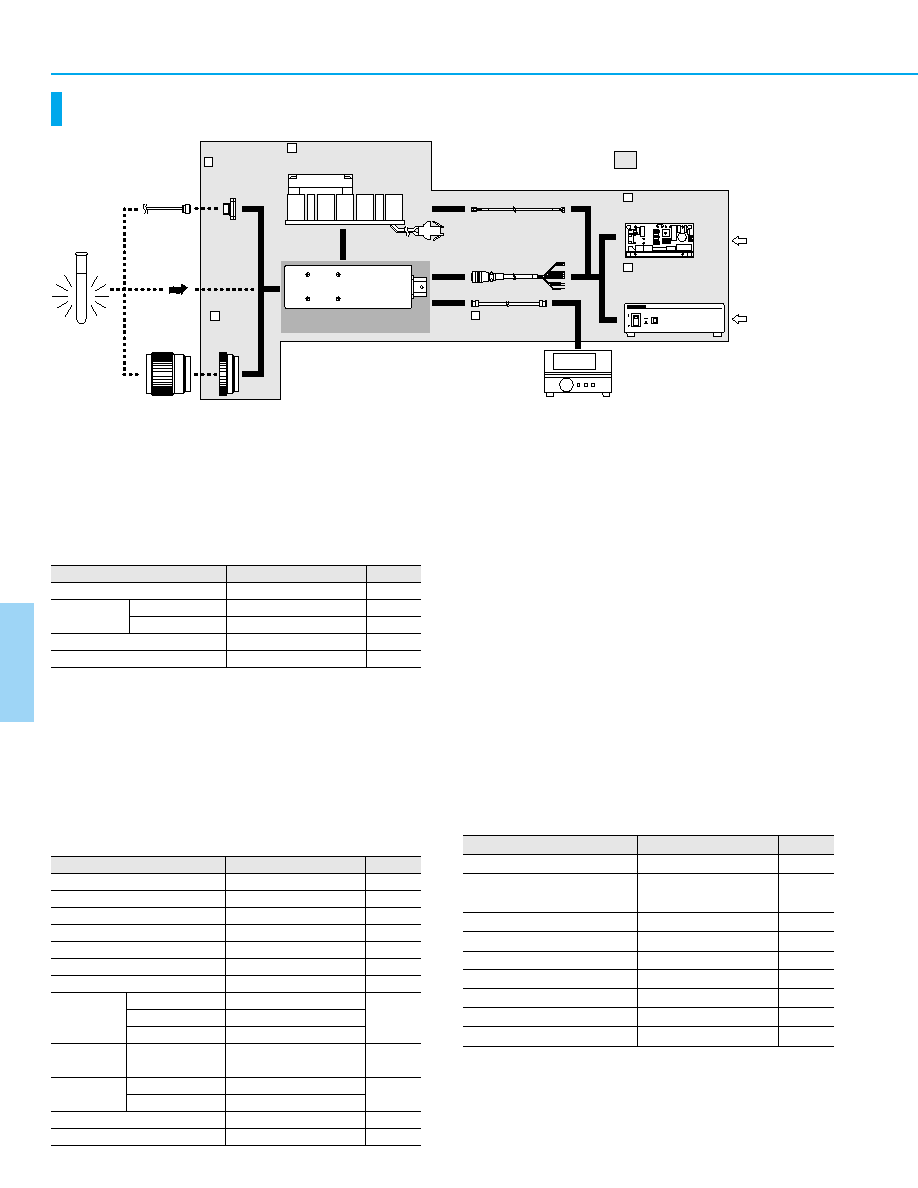
Options for H7421 Series
TPHOC0040EE
G Heatsink with Fan A7423
The temperature of the H7421 outer case rises due to the
thermoelectric cooler housed in the case. The A7423 heatsink
efficiently radiates away this heat to prevent a temperature
rise in the H7421. The A7423 can be easily installed onto the
H7421 with four M3 screws. Apply a coat of heat conductive
grease onto the joint surface shared by the H7421 and
A7423.
G Signal Cable E1168-05
This signal cable comes attached to a BNC connector for
easily connecting the H7421 to external equipment.
G Optical Fiber Adapter (FC Type) A7412
The A7412 is an FC type optical fiber connector that attaches
to the light input window of the H7421. The A7412 can easily
be secured in place with four M2 screws.
G C-Mount Adapter A7413
The A7413 mount adapter is used when a C-mount lens pro-
truding 4 mm or more from the flange-back must be installed
onto the H7421.
G Power Supply Unit with Temperature Control C8137
The C8137 is a power supply unit with a temperature control
function. Just connecting to an AC source of 100 V to 240 V
generates the output voltages for the thermoelectric cooler
and the A7423 fan, needed for operating the H7421. The pho-
tomultiplier tube temperature can be maintained to 0
∞C by
monitoring the thermistor and regulating the output current for
the thermoelectric cooler.
SOLD SEPARATELY
INPUT
12 V
INPUT
AC 100 V to
AC 240 V
POWER SUPPLY UNIT
with TEMPERATURE
CONTROL M9011
SIGNAL CABLE
E1168-05
COUNTER
CABLES
(Included with M9011
or C8137)
HEATSINK with FAN
A7423
OPTICAL FIBER
ADAPTER
A7412
C-MOUNT
ADAPTER
A7413
OPTICAL
FIBER
DIRECT INPUT
C-MOUNT
LENS
SAMPLE
PHOTONCOUNTING HEAD
H7421 SERIES
1
4
5
3
2
POWER SUPPLY UNIT
with TEMPERATURE CONTROL
C8137
6
ON
ON
CHK4
CN5
CHK3
SW1
ON
SW2
Don't use
Vcont-ADJ
CN04
CN03
CHK2
CHK1
CN01
Vcont
GND
6 5 4 3 2
1
G Power Supply Unit with Temperature Control M9011
The M9011 is an on-board type power supply unit.
By just connecting to 12 V supply, the M9011 provides power
necessary to operate the H7421 series. The M9011 also
controls the thermoelectric cooler in the H7421 series so that
the output and noise can be maintained at constant levels
even when the ambient temperature changes. The
thermoelectric cooler and PMT operation can be controlled
from an external device by connecting it to the I/O connector
on the M9011.
Parameter
Value
Max. Cooling Temperature (
T)
Input Voltage
Max. Input Current
Max. Power Consumption
Main Circuit Output Voltage
Max. Output Current for Thermoelectric Cooler
Output Voltage for Fan
Control Signal
Input Voltage
Error Signal
Output Voltage
LED Output
Setting Cooling Temperature
Weight (excluding cables)
Thermoelectric Cooler
PMT
Fan
Thermoelectric
Cooler
PMT
Error
35
12
1.2
15.8
5
2.2
12
Non-insulated TTL level input
Non-insulated TTL level input
Non-insulated TTL level input
Non-insulated TTL level output
5
5
0
120
Unit
∞C
V
A
V∑A
V
A
V
--
--
V
∞C
g
Parameter
Value
Input Voltage
Input Current
Operating Voltage
Weight
12
140
90
10.2 to 13.8
120
Unit
V
mA
mA
V
g
During Lock
During Operation
Parameter
Value
Max. Cooling Temperature (
T)
Setting Cooling Temperature
(preset at factory)
Input Voltage
Input Voltage Frequency
Power Consumption
Main Circuit Output Voltage
Max. Current for Thermoelectric Cooler
Output Voltage for Fan
Weight
35
0
AC 100 to AC 240
50/60
30
+5
2.2
12
1
Unit
∞C
∞C
V
Hz
V∑A
V
A
V
kg

43
Photon Counting Heads H7421 Series
Options
(Unit: mm)
TACCA0188ED
TACCA0190EB
TACCA0191EA
TACCA0237EB
TACCA0252EA
TACCA0148EA
Power Supply Unit with Temperature Control M9011
Heatsink with Fan A7423
Optical Fiber Adapter (FC Type) A7412
C-Mount Adapter A7413
Signal Cable E1168-05
4
14
M25.4 P=1/32" C-MOUNT
30
M25.4 P=1/32" C-MOUNT
22
8
1500
+50
- 0
BNC-P
BNC-P
1
3
4
5
2
Power Supply Unit with Temperature Control C8137
6
JST XMR-02V
16.5
±
0.3
22.2
±
0.2
52.0
±
0.5
TOP VIEW
SIDE VIEW
4-M3 (SUPPLIED)
24.5
±
0.5
40
±
1
19.2
± 0.3
53.6
± 0.3
92.0
± 0.5
LEAD LENGTH 50
± 10
FAN CABLE
POWER CABLE
EXTERNAL
I/O CABLE
EXTERNAL
I/O HOUSING
MODULE CABLE
1500
± 50
1500
± 50
1000
± 50
1000
± 50
CHK4
CN5
CHK3
SW1
ON
SW2
Don't use
Vcont-ADJ
CN04
CN03
CHK2
CHK1
CN01
Vcont
GND
6
5
4
3
2
1
4-M2
50.0
±
0.2
28.0
± 0.2
70.0
± 0.1
15.0
± 0.1
40.0
±
0.1
5.0
±
0.1
100.0
± 0.3
M8 P=0.75
9.5
15
5.5
3
9
4- 2.2
4 TAPERED DEPTH 1.5
3.0
2.5
4-M2 L=3
LIGHT SHIELD SHEET
(THICKNESS: 0.5)
SIDE VIEW
FRONT VIEW
1500
1500
1800 to 2000
POWER CABLE
FAN CABLE
AC CABLE
ON
ON
46.0
±
0.5
MODULE OUTPUT
AC INPUT
FAN OUTPUT
PHOTOSENSOR SWITCH
POWER
FUSE
42
8
212
± 1
12.5
160.0
± 0.5
FRONT VIEW
SIDE VIEW
REAR VIEW
+50
-0
+50
-0