34
Specifications
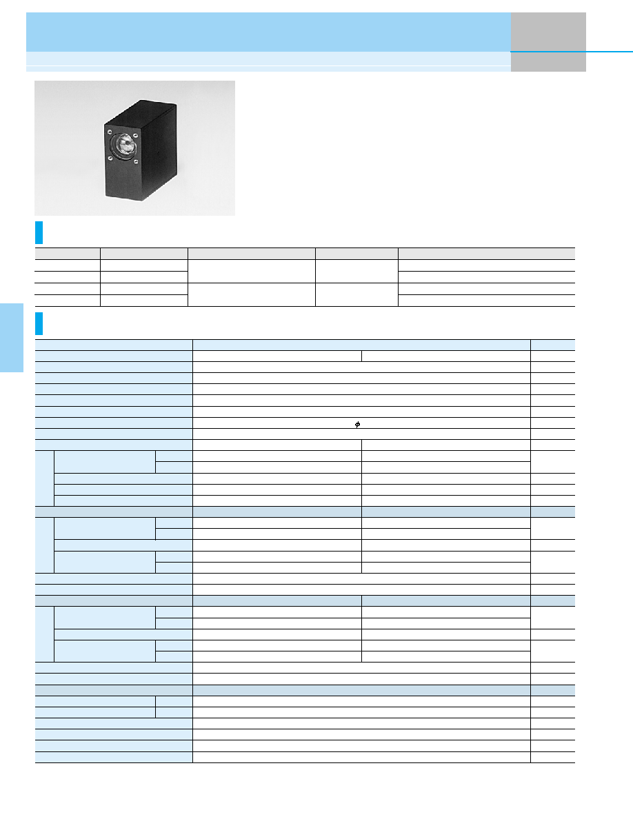
The H7827 series photosensor modules incorporate a 19-mm (3/4") diameter
head-on photomultiplier tube, a high-voltage power supply circuit and a low
noise amplifier. Two types of amplifiers are available with a current-to-voltage
conversion factor of 1 V/
µA or 0.1 V/µA and a frequency bandwidth of DC to
20 kHz or DC to 200 kHz. Two types of photomultiplier tubes with different
spectral response characteristics are provided for measurement in the visible
range or visible to near IR range.
Compact Head-on PMT
Photosensor Modules H7827 Series
Product Variations
Cathode
Anode
Anode
300 nm to 650 nm
300 nm to 850 nm
300 nm to 650 nm
300 nm to 850 nm
Spectral Response
H7827-001
H7827-011
H7827-002
H7827-012
For general applications in visible range
For visible to near IR range
For general applications in visible range
For visible to near IR range
Type No.
1 V/
µA
0.1 V/
µA
Current-to-Voltage Conversion Factor
DC to 20 kHz
DC to 200 kHz
Frequency Bandwidth
Features
Parameter
Suffix
Input Voltage
Max. Input Voltage
Max. Input Current
Max. Control Voltage
Recommended Control Voltage Adjustment Range
Effective Area
Sensitivity Adjustment Range
Peak Sensitivity Wavelength
Suffix (with internal 20 kHz amp)
Max. Output Signal Voltage
Current-to-Voltage Conversion Factor
Suffix (with internal 200 kHz amp)
Max. Output Signal Voltage
Current-to-Voltage Conversion Factor
Offset Voltage *
2
Ripple Noise *
2
*
4
(peak to peak)
Settling Time *
5
Operating Ambient Temperature
Storage Temperature
Weight
±11.5 to ±15.5
±18
+40/-1
+1.2 (Input Impedance 100 k
)
+0.5 to +1.1
15
1: 10
3
+10 (Load resistance 10 k
)
1
+10 (Load resistance 10 k
)
0.1
-001 / -002
420
60
90
10.5
--
85
-001
1.0
◊ 10
7
5.0
◊ 10
7
47
3
20
-002
1.0
◊ 10
6
5.0
◊ 10
6
4.7
0.3
2
-011 / -012
380
80
120
--
0.2
49
-011
1.0
◊ 10
7
3.0
◊ 10
7
13
3
20
-012
1.0
◊ 10
6
3.0
◊ 10
6
1.3
0.3
2
Unit
--
V
V
mA
V
V
mm
--
nm
µA/lm
--
--
mA/W
V/lm
V/nW
mV
V
V/
µA
V/lm
V/nW
mV
V
V/
µA
mV
mV
s
∞C
∞C
g
H7827 Series
Min.
Typ.
Min.
Typ.
Typ.
Max.
Min.
Typ.
Typ.
Max.
Typ.
Max.
Luminous Sensitivity
Blue Sensitivity Index (CS 5-58)
Red/White Ratio
Radiant Sensitivity
*
1
Luminous Sensitivity *
2
Radiant Sensitivity *
1
*
2
Voltage Output Depending
on PMT Dark Current *
2
*
3
Luminous Sensitivity *
2
Radiant Sensitivity *
1
*
2
Voltage Output Depending
on PMT Dark Current *
2
*
3
±3
4
0.2
+5 to +45
-20 to +50
80
H7827 series
*1: Measured at the peak sensitivity wavelength *2: Control voltage = +1.0 V *3: After 30 minute storage in darkness
*4: Cable RG-174/U, Cable length 450 mm, Load resistance = 1 M
, Load capacitance = 22 pF
*5: The time required for the output to reach a stable level following a change in the control voltage from +1.0 V to +0.5 V.

35
Characteristics
(Anode radiant sensitivity, PMT gain)
Sensitivity Adjustment Method
Dimensional Outlines
(Unit: mm)
TPMOC0166EB
TPMOA0023EB
TPMOB0156EA
TPMOB0159EA
200
100
400
300
600
500
800
700
0.1
1
10
900
0.01
0.01
0.1
1
H7827-002
-012
H7827-001
-011
0.001
WAVELENGTH (nm)
ANODE RADIANT SENSITIVITY (V/nW)
ANODE RADIANT SENSITIVITY (V/nW)
-011
-012
-001
-002
PMT GAIN: 10
5
10
7
10
8
10
6
10
5
10
4
10
3
10
2
0.25
0.5
0.3
0.7
1.0
1.5
2.0
0.4
1.2
CONTROL VOLTAGE (V)
PMT GAIN
-001
-002
-011
-012
+15 V
-15 V
GND
+15 V
-15 V
GND
SIGNAL OUTPUT
COAXIAL CABLE
RED (LOW VOLTAGE INPUT)
GREEN (LOW VOLTAGE INPUT)
BLACK (GND)
BLUE (Vref OUTPUT)
WHITE (Vcontrol INPUT)
SIGNAL OUTPUT
PHOTOSENSOR MODULE
POWER SUPPLY
POWER SUPPLY
PHOTOSENSOR MODULE
+0.5 V to
+1.1 V
POTENTIOMETER (10 k
)
MONITOR
CW
VOLTAGE PROGRAMMING
RESISTANCE PROGRAMMING
∑ Adjust the control voltage to
adjust the sensitivity.
∑ Electrically insulate the
reference voltage output.
When using a potentiometer, adjust sensitivity
while monitoring the control voltage.
COAXIAL CABLE
RED (LOW VOLTAGE INPUT)
GREEN (LOW VOLTAGE INPUT)
BLACK (GND)
BLUE (Vref OUTPUT)
WHITE (Vcontrol INPUT)
GND
50.0
+1.0
14.0
±
0.5
25.0
±
0.5
18.6
±
0.7
13.0
± 0.5
18
4-M2
DEPTH: 5
26.0
+0.5
- 0
56.0
0
+0.5
- 0
+0.1
- 0.3
10.0
± 0.5
16.0
± 0.5
- 0
2-M3 DEPTH: 5
SIGNAL OUTPUT
BNC-R
POWER INPUT
HIROSE HR10A-7R-6P
1: GND
2: Vcc +15 V
3: Vcont +0.5 V to +1.1 V
4: Vref
5: NC
6: Vee -15 V
EFFECTIVE AREA
15 Min.
SIDE VIEW
FRONT VIEW
REAR VIEW
18.0
±
0.5
19.0
±
0.5
Power cable with connector (HIROSE HR10A-7P-6S) is supplied with the H7827 series
700
± 20
BLACK:
RED:
WHITE:
BLUE:
GREEN:
GND
LOW VOLTAGE INPUT (+15 V)
Vcont INPUT (+0.5 V to +1.1 V)
Vref OUTPUT (+1.2 V)
LOW VOLTAGE INPUT (-15 V)
Voltage Output Type Photosensor Modules