Type No.
H7710-11
H7710-12
H7710-13
H7710-14
H7710-15
H8567-01
H8567-02
H8567-03
H8567-04
H8567-05
185 nm to 750 nm
185 nm to 900 nm
185 nm to 900 nm
185 nm to 830 nm
185 nm to 650 nm
High sensitivity in UV to visible range
For general applications in UV to near IR range
High sensitivity in UV to near IR range
Low dark current in UV to near IR range
For general applications in UV to visible range
Spectral Response
Features
22
Product Variations
Specifications
The H7710/H8567 series photosensor modules contain a high-voltage power
supply circuit and a 13-mm (1/2") diameter side-on photomultiplier tube in a
compact aluminum housing. The 13-mm (1/2") side-on photomultiplier tube
has a reflection mode photocathode that delivers high quantum efficiency at
wavelengths above 600 nm, an adequate gain of up to 10
7
and fast time
response. A high S/N ratio can be obtained even when measuring extremely
low level light at high speeds.
The H7710 series uses a Cockcroft-Walton circuit with low power
consumption, while the H8567 series has a high-voltage power supply circuit
comprised of a Cockcroft-Walton circuit and an active divider circuit to shorten
the settling time. Select the desired type that meets your application. Five
types are available according to the required spectral response range. Flexible
cables are used for easy installation in equipment.
Compact Side-on PMT
Photosensor Modules H7710/H8567 Series
*1: Measured at the peak sensitivity wavelength *2: Control voltage = +1.0 V *3: After 30 minute storage in darkness
*4: Cable RG-174/U, Cable length 450 mm, Load resistance = 1 M
, Load capacitance = 22 pF
*5: The time required for the output to reach a stable level following a change in the control voltage from +1.0 V to +0.5 V.
Parameter
H7710 / H8567 Series
Input Voltage
Max. Input Voltage
Max. Input Current
Max. Output Signal Current
Max. Control Voltage
Recommended Control Voltage Adjustment Range
Effective Area
Sensitivity Adjustment Range
Peak Sensitivity Wavelength
Rise Time *
2
Ripple Noise *
2
*
4
(peak to peak)
Settling Time *
5
Operating Ambient Temperature
Storage Temperature
Weight
+11.5 to +15.5
+18
7
25
10
+1.2 (Input impedance H7710 Series: 1 M
, H8567 Series: 100 k)
+0.25 to +1.0
3.7
◊ 13.0
1: 10
4
450
350
500
--
0.4
105
1000
2000
4.2
◊ 10
5
2
10
1.4
-20 to +50
100
420
80
120
10
--
90
100
700
5.2
◊ 10
5
1
10
400
200
300
--
0.3
77
400
2000
5.2
◊ 10
5
1
10
530
140
200
--
0.15
70
300
700
2.5
◊ 10
5
0.1
1
Suffix
-13
-03
-11
-01
-12
-02
-14
-04
--
-15
-05
340
20
40
5
--
48
50
300
3.6
◊ 10
5
0.5
5
Unit
V
V
mA
µA
V
V
mm
--
nm
µA/lm
--
--
mA/W
A/lm
A/W
nA
ns
mV
s
∞C
∞C
g
Luminous Sensitivity
Blue Sensitivity Index (CS 5-58)
Red/White Ratio
Radiant Sensitivity *
1
Luminous Sensitivity *
2
Radiant Sensitivity *
1
*
2
Dark Current *
2
*
3
Min.
Typ.
Min.
Typ.
Typ.
Max.
Max.
H7710 Series
H8567 Series
H7710 Series
H8567 Series
H7710 Series
H8567 Series
0.6
10
+5 to +50
0.6
0.2
+5 to +45
Cathode
Anode
23
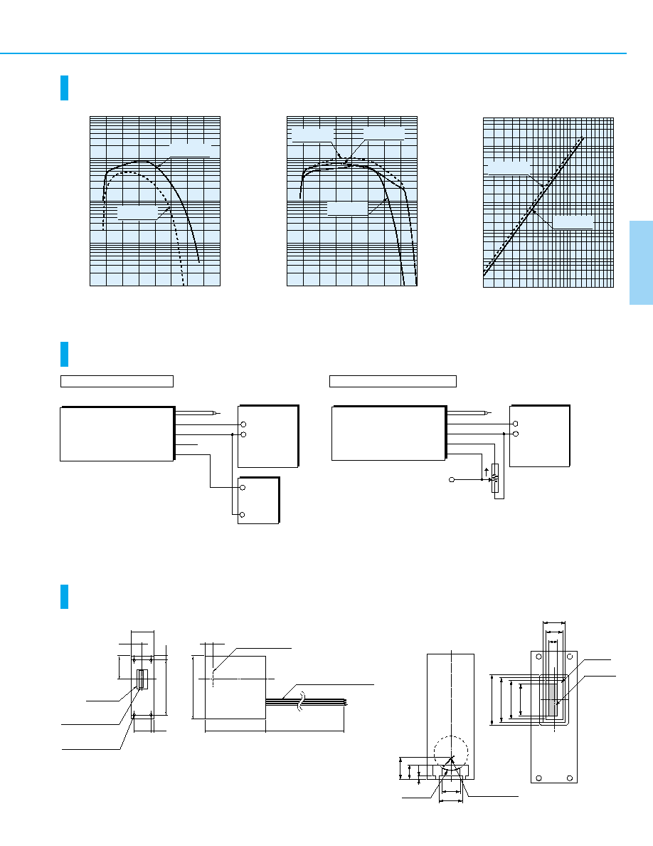
Characteristics
(Cathode radiant sensitivity, PMT gain)
Sensitivity Adjustment Method
Dimensional Outlines
(Unit: mm)
TPMOB0138EB
TPMOB0139EB
TPMOB0140EB
TPMOC0146EB
TPMOA0013ED
TPMOA0018ED
Details of input window
Voltage Programming
Resistance Programming
WAVELENGTH (nm)
CA
THODE RADIANT SENSITIVITY (mA/W)
100
1000
100
200
300
400
500
600
700
900
800
10
1
0.1
H7710-11
H8567-01 Type
H7710-15
H8567-05 Type
WAVELENGTH (nm)
CA
THODE RADIANT SENSITIVITY (mA/W)
1000
100
200
300
400
500
600
700
900
800
100
10
1
0.1
H7710-12
H8567-02 Type
H7710-13
H8567-03 Type
H7710-14
H8567-04 Type
CONTROL VOLTAGE (V)
PMT GAIN
10
7
10
8
10
6
10
5
10
4
10
3
10
2
0.25
0.5
0.3
0.7
1.0
1.5
2.0
H7710-15
H8567-05 Type
H7710-11
H8567-01 Type
+15 V
GND
+15 V
GND
SIGNAL OUTPUT
GND
COAXIAL CABLE
RED (LOW VOLTAGE INPUT)
BLACK (GND)
BLUE (Vref OUTPUT)
WHITE (Vcontrol INPUT)
SIGNAL OUTPUT
PHOTOSENSOR MODULE
POWER SUPPLY
POWER SUPPLY
PHOTOSENSOR MODULE
+0.25 V to
+1.0 V
COAXIAL CABLE
RED (LOW VOLTAGE INPUT)
BLACK (GND)
BLUE (Vref OUTPUT)
WHITE (Vcontrol INPUT)
POTENTIOMETER (10 k
)
MONITOR
CW
∑ Electrically insulate the
reference voltage output.
∑ Adjust the control voltage to
adjust the sensitivity.
When using a potentiometer, adjust sensitivity
while monitoring the control voltage.
19.7
53.2
±
0.5
EFFECTIVE
AREA
(3.7
◊ 13.0)
50.8
± 0.5
450
± 20
49.0
±
0.5
9.5
2.1
3.5
12.0
± 0.2
FRONT VIEW
SIDE VIEW
MOUNTING
THREADED HOLE
(4-M2 DEPTH: 4)
19.0
± 0.5
8.8
WINDOW
(7
◊ 16)
COAX CABLE
OTHER WIRES
: RG-174/U
: AWG 26
PHOTOCATHODE
16
13
18
20.5
8.8
6.0
1.5
7
3.7
9
WINDOW
EFFECTIVE
AREA
(3.7
◊ 13.0)
PHOTOCATHODE
WINDOW
9
7
TOP VIEW
FRONT VIEW
Current Output Type Photosensor Modules