HAMAMATSU CORPORATION
HC125-08 Rev 0
Proprietary to: General
March 1993
PRODUCT SPECIFICATIONS
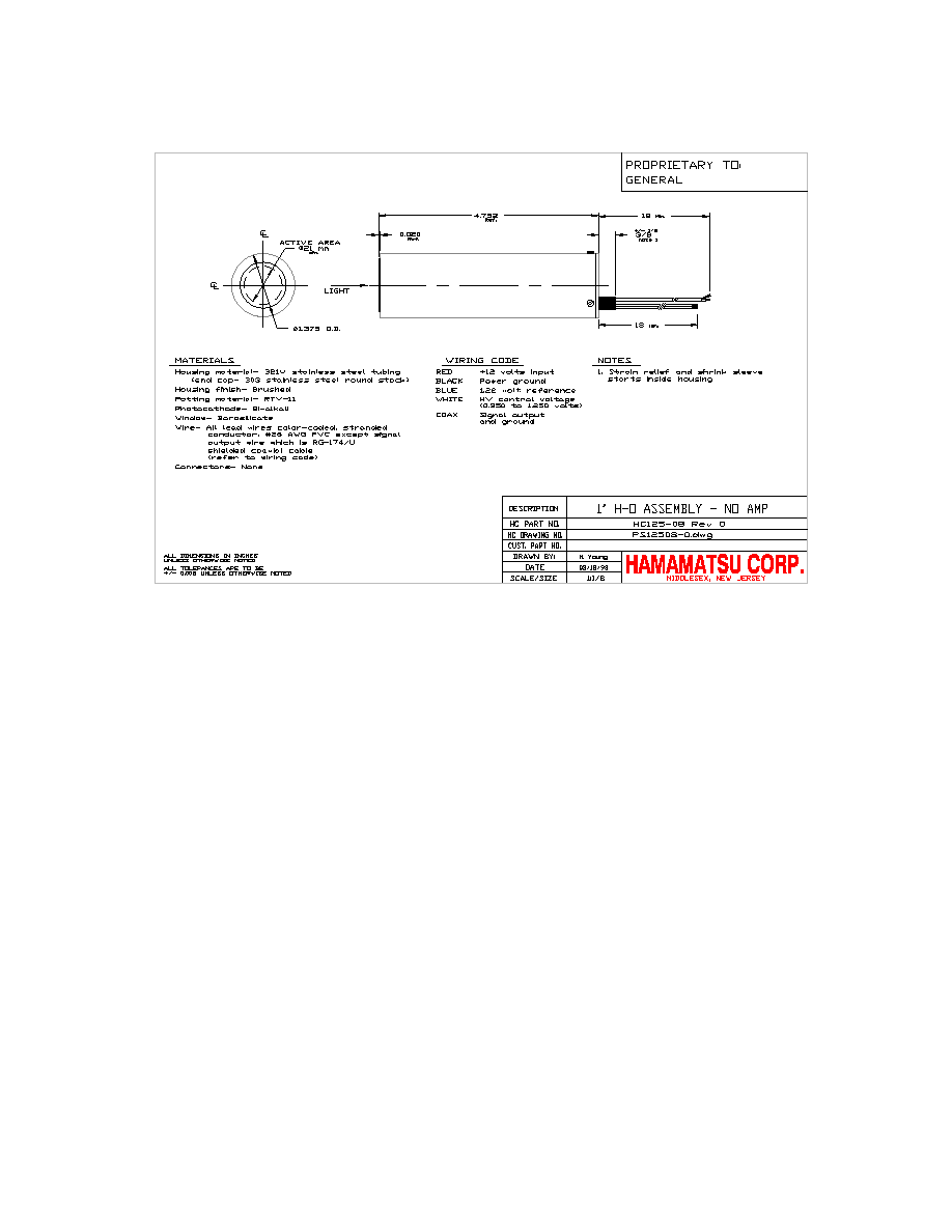
Product Description: PMT based detector assembly with 1 inch head-on PMT,
R1924 and high voltage power supply
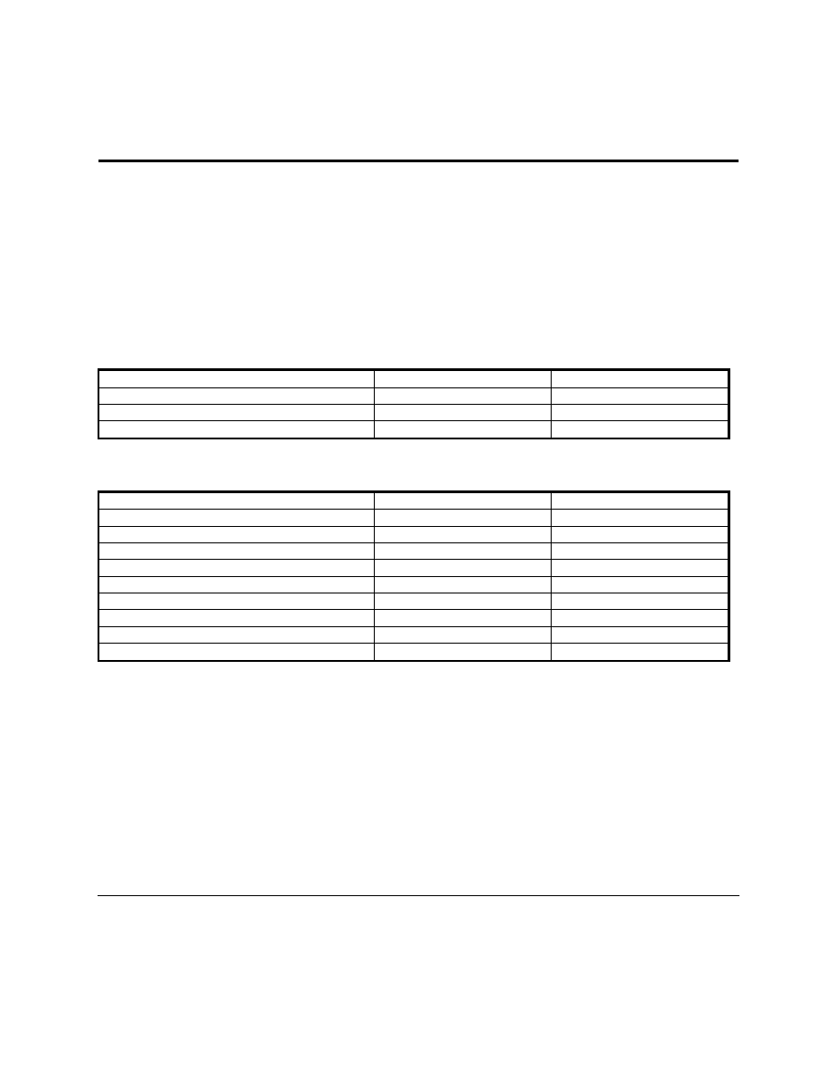
MAXIMUM RATINGS
1
HV output voltage
-1250
volts
Supply voltage
+/- 18
volts
Operating temperature
+5 to +50
O
C
Storage temperature
-20 to +50
O
C
GENERAL SPECIFICATIONS
Wavelength range
300 to 850
nm
HV output voltage range
2
-350 to -1200
volts
Supply voltage range
+/- 11.5 to +/- 15.5
volts
HV output/input ratio
1000 to 1
volts/volt
Voltage divider ratio
3:1:1:1:1:1:1:1:1:1:1
volts/volt
Warm-up time
10
minutes
Output voltage decay time constant
3
20
seconds
Active area
21 diameter
millimeter, min.
Overall dimensions (less projections)
1.375 diam. x 4.752
inch
Weight
300
grams, typ.
See drawing No. PS12508-0.dwg for additional mechanical and wiring specifications.
NOTES
1. Stresses above the Maximum Ratings may cause permanent damage to the device. Exposure to maximum conditions
for extended periods may reduce device reliability.
2. Measurement of the high voltage (at the photocathode) is achieved by measuring the voltage at the monitor input and
multiplying by 1000 for an accuracy of within 1% at the photocathode.
3. The gain of the PMT decays ten times faster than the output voltage.
HC125-08 Rev 0
HAMAMATSU
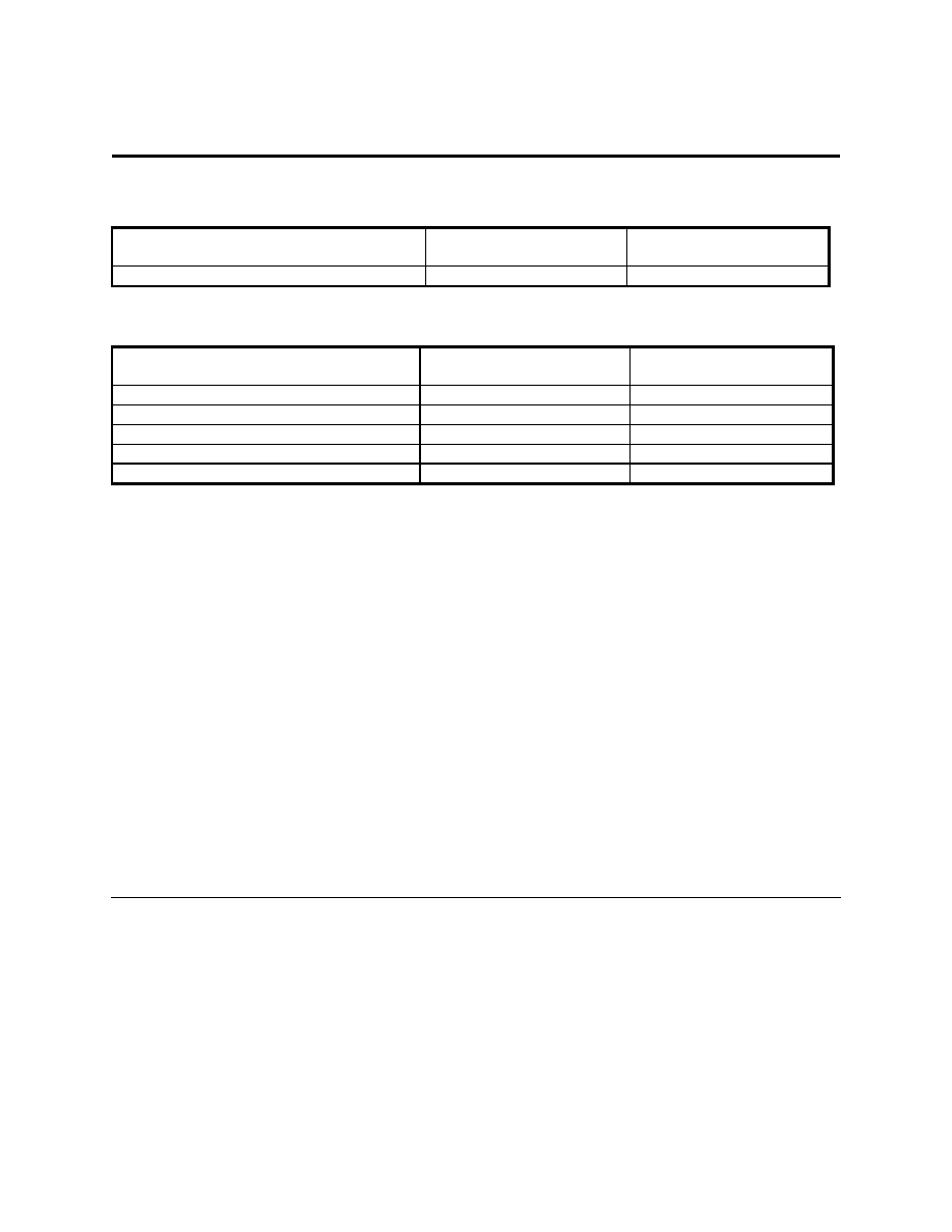
PHOTOMULTIPLIER SPECIFICATIONS
1
Cathode luminous sensitivity, Sk
60
90
uA/lm, min.
uA/lm, typ.
Anode luminous sensitivity, Sp
100
A/lm, typ
PERFORMANCE SPECIFICATIONS (25
O
C, -1000 VOLTS)
Supply current
2
@ +12 volts input
7.0
mA, max.
Temperature coefficient of high voltage
3
100
ppm /
O
C, typ.
Linearity of anode signal current @ 20 uA
4
1
%, typ.
Anode ripple interference
5
1
mV, max
Current limit (HV supply circuit)
20
mA, typ.
Responsivity @ 420 nm
80E3
amps/watt, typ.
NOTES
1. The Photomultiplier tube used in this assembly meets all specifications and should be used with the limitations listed in
the Hamamatsu Photonics, Japan general data sheet.
2. Current consumption increases if high light levels are applied to the Photomultiplier tube.
3. This is an average measurement. The maximum voltage is subtracted from the minimum voltage over the specified
temperature range and divided by the temperature difference.
4. This measurement is for DC light input. Tube characteristics such as gain drop or hysteresis may cause additional
inaccuracies when measuring high light levels at high signal current levels.
5. This is measured with the 18 inch coax signal lead connected to an unterminated scope having 20 pF input capacitance
and 1 megohm input resistance. For lower load resistance or more capacitance (i.e. lower gain or bandwidth), the
ripple interference becomes proportionally less.