HC124/HC125 Series
HC124/HC125 Series
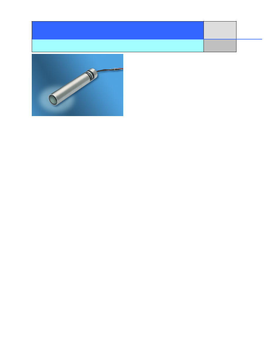
Module for 1 1/8" & 1" Head-On Photomultiplier Tubes
Module for 1 1/8" & 1" Head-On Photomultiplier Tubes
FEATURES:
∑
COMPACT SIZE
∑
LOW POWER CONSUMPTION FOR
BATTERY OPERATION
∑
NO EXPOSURE TO HIGH VOLTAGE
WIRING
∑
SUPPLY ONLY LOW VOLTAGE
∑
RUGGED, POTTED HOUSING
HC124-01 Includes 1 1/8" multi-alkali PMT with 8 MHz amplifier
HC124-02 Includes 1 1/8" bialkali PMT with 8 MHz amplifier
HC124-03 Includes 1 1/8" bialkali PMT with photon counting circuit
HC125-01 Includes 1" multi-alkali PMT with 8 MHz amplifier
HC125-02 Includes 1" bialkali PMT with 8 MHz amplifier
The HC124 and HC125 Series of integrated detector assemblies combines either a 1" (HC125 Series) or
a1 1/8" (HC124 Series) head-on photomultiplier tube with a high voltage power supply, divider and signal
processing circuitry for the measurement of weak light signals. The user needs only to supply low voltage to
operate the assembly. Two types are available as standard:
HIGH SPEED PULSE: An 8 mHz current to voltage, transimpedance amplifier is used to change the weak
current output of the PMT to a voltage of low output impedance. This signal processing if for high speed
light pulses or scanning applications.
PHOTON COUNTING: Current pulses from individual photons are amplified sufficiently to be discriminated
against noise by a high speed comparator. This is the most sensitive light measurement technique.
The voltage needed to power the photomultiplier tube is based upon the Cockroft-Walton voltage
multiplier with one stage per dynode. The voltage multiplier also performs the voltage division normally
accomplished with a resistive divider, significantly reducing power consumption and offering higher signal
output current with improved linearity.
The photomultiplier tube and circuitry are potted within a stainless steel housing to guard against moisture
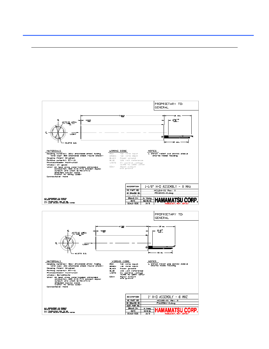
and contamination as well as to protect the PMT from shock and vibration. The housing is 7 Ω inch long for
the HC124 Series and 4 7/8" long for the HC125 Series. These assemblies can be made with a wide variety
of 1" or 1 1/8" head-on PMT's as well as different amplifier gain and bandwidth specifications. Please
consult the factory on the availability of these special assemblies.

MAXIMUM RATINGS
1
PARAMETER
HC124
HC125
UNITS
HV output voltage
-1250
volts
Supply voltage
+/- 18
volts
Operating temperature
+5 to +50
O
C
Storage temperature
-20 to +50
O
C
Wavelength range
185 to 850
300-850
nm
HV output voltage range
2
-350 to ≠1200
volts
Supply voltage range
±11.5 to ±15.5
volts
HV output/input ratio
1000 to 1
volts/volt
Voltage divider ratio
2:1:1:1:1:1:1:1:1:1:1:1
3:1:1:1:1:1:1:1:1:1:1
volts/volt
Warm-up time
10
minutes
Output voltage decay time constant
3
20
seconds
Active area
25 dia.
21 dia.
mm, min.
Overall dimensions (less projections)
1.375 dia. x 7.562
1.375 dia. x 4.752
inch
Weight
350
300
grams, typ.
NOTES
1.
Stresses above the Maximum Ratings may cause permanent damage to the device. Exposure to maximum conditions for extended periods
may reduce device reliability.
2.
Measurement of the high voltage (at the photocathode) is achieved by measuring the voltage at the monitor input and multiplying by 1000
for an accuracy of within 1% at the photocathode.
3.
The gain of the PMT decays ten times faster than the output voltage.
PHOTOMULTIPLIER SPECIFICATIONS
1
PARAMETER
HC124
HC125
UNITS
Cathode luminous sensitivity, S
k
80
150
80
120
ÏA/lm, min.
ÏA/lm, typ.
Anode luminous sensitivity, S
p
80
30
A/lm, typ
PERFORMANCE SPECIFICATIONS (25∞C, -1000 volts, R
L
=500Ÿ)
PARAMETER
HC124
HC125
UNITS
Supply current
2
@ +12 volts input
@ -12 volts input
18.0
13.0
mA, typ.
mA, typ.
Temperature coefficient of high voltage
3
100
ppm /
O
C, typ.
Linearity of anode signal current @ 20 ÏA
4
1
%, typ.
Amplifier transimpedance
100,000
ohms
Amplifier bandwidth @ -3 dB
8.0
MHz, min.
Amplifier noise
20
mV p-p, typ.
Peak output signal
5
@ R
L
= 500 ohm
@ R
L
= 50 ohm
8
2
volts, max.
volts, max.
Rise time
30
ns, typ.
Fall time
50
ns, typ.
Current limit (HV supply circuit)
20
mA., typ.
Responsivity @ 420 nm
3
1.1
volts/nW, typ.
NOTES
1.
The photomultiplier tube used in this assembly meets all specifications and should be used with the limitations listed in the Hamamatsu
Photonics, Japan general data sheet.
2.
Current consumption increases if high light levels are applied to the photomultiplier tube.
3.
This is an average measurement. The maximum voltage is subtracted from the minimum voltage over the specified temperature range and
divided by the temperature difference.
4.
This measurement is for DC light input. Tube characteristics such as gain drop or hystersis may cause additional inaccuracies when
measuring high light levels at high signal current levels.
5.
This applies for pulse applications where the duty factor is less than 0.25. The average output voltage should be limited to 2 volts @ R
L
=
500 ohm and 1 volt @ R
L
= 50 ohm, respectively.