 | –≠–ª–µ–∫—Ç—Ä–æ–Ω–Ω—ã–π –∫–æ–º–ø–æ–Ω–µ–Ω—Ç: L2D2 | –°–∫–∞—á–∞—Ç—å:  PDF PDF  ZIP ZIP |
PATENTS
The best light source is supported by the best electrode technology.
DEUTERIUM LAMPS
L2D2
LAMPS

LONG LIFE : 4000
HOURS
4 times longer guaranteed life
I Life Characteristics
TIME(hours)
LIGHT INTENSITY (%)
4000
3000
2000
1000
0
0
100
50
HIGH LIGHT OUTPUT : 1.3
TIMES HIGHER
1.1 times higher (L2-4000 series)
I Radiant Output Intensity
L2D2LAMP L2-2000 SERIES
1.3 TIMES HIGHER
(L2-2000 Series)
HIGH STABILITY : 2
TIMES STABLE
Fluctuation: 0.05 %p-p, Drift:
±
0.3 %/h
TIME (30 s/div.)
I Light Output Stability
TLSOB0051EA
1
◊10
-5
AU
L2D2 LAMPS
CONVENTIONAL LAMPS
EXCELLENT
TEMPERATURE
CHARACTERISTICS
LESS MOVEMENT
OF ARC
EMISSION POINT
SMALL INTENSITY VARIATIONS : 1/2
Compared to our conventional lamps
I Intensity Variation
TLSOB0053EA
TLSOF0138
TLSOB0052EA
HPLC
Atomic Absorption Spectrophotometers
Thin Layer Chromatography
UV-VIS Spectrophotometers
CE(Capillary Electrophoresis)
SOx/NOx Analyzers
Film Thickness Measurement
APPLICATIONS
L2D2 Lamps
(Deuterium Lamps )
The L2-4000 series lamps
assure an operating life of
4000 hours-4 times longer
than conventional lamps.
This is the longest operat-
ing life of any deuterium
lamp.
The L2-2000 series lamps
produce 1.3 times higher
light output than conven-
tional lamps. The L2-4000
series lamps even offer
light output 1.1 times higher
than conventional lamps.
By using a newly devel-
oped ceramic structure, a
uniform and optimum tem-
perature
distribution, which
are the most important
factor for stable operation,
can be obtained. This
results in fluctuations of
only 0.05 %p-p in the light
output, as well as a re-
duced drift of only
±0.3 %/h.
Use of a ceramic structure with excellent thermal
stability ensures stable lamp operation even in
the presence of ambient temperature variations.
The spacing between elec-
trodes is kept fixed by a
molded ceramic spacer.
This reduces the lamp to
lamp variations in the light
output to one half of that
obtained with our lamps
having a conventional all
metal structure.
Since the ceramic structure has a small thermal
expansion coefficient, there is virtually no move-
ment of the arc emission point during operation.
TLSOB0050EA
WAVELENGTH (nm)
190
RELATIVE INTENSITY(A.U.)
0
0.5
1
1.5
2
2.5
3
3.5
4
210
230
250
270
290
310
330
350
370
390
L2D2 LAMPS
CONVENTIONAL
LAMPS
L2-2000
SERIES
L2D2 LAMP
L2D2 LAMP
L2-4000
SERIES
CONVENTIONAL
TYPE
CONVENTIONAL
TYPE
1
2
WAVELENGTH(nm)
LIGHT INTENSITY (A.U.)
390
370
350
330
310
0
1
2
3
4
290
270
250
230
210
190

General Purpose
3.0 V/0 V to 1 V
2.5 V/1.7 V
10 V/2.5 V to 6.0 V
10 V/7.0 V
12 V to 15 V/0 V
2.5 V/1.0 V
2.5 V/1.0 V
2.5 V/1.0 V
2.5 V/1.7 V
L2-2000
L2-2000
L2-4000
See-through
30W
3.0 V/0 V to 1 V
Power
Consumption
Type
Series
Cathode Rating
GENERAL PURPOSE
SEE-THROUGH TYPE
NOTE
NOTE
ALamps with an aperture of 0.5 mm diameter are high brightness types. These lamps provide 1.6 times higher brightness than standard lamps with an aperture of 1.0 mm diameter. (Refer to page 8.)
BA trigger voltage higher than this value is required to start lamp discharge. For reliable lighting, an application of 500 V to 600 V is recommended. The maximum rated voltage that can be applied is 650 V.
CThe heater current during warming-up period is so high that the enough voltage may not be supplied to the lamp in case the cable between the lamp and the power supply is long because
of voltage drop at the cable. The power supply for the heater should be designed so as to supply specified voltage at the lamp terminal.
DThe lamp life end is defined as the point when the light output falls to 50 % of its initial value or when output fluctuation (p-p) exceeds 0.05 %.
EL2D2 lamp does not always have a direct replacement for conventional type from its dimensional outline point of view. Please refer to page 5 and 6. Please consult with our sales offices
for further details.
An Example for optics of See-through type
The see-through type electrode structure enables
straight-line arrangement of the halogen lamp, deuterium
lamp, optical system and optical passage. This simplifies
optical design of UV-VIS spectrophotometer etc., and
eliminates loss of light amount caused by the half mirror.
SEE-THROUGH TYPE
L2D2 Lamps
(Deuterium Lamps )
FRecommended operating voltage is 3.5 V
± 0.5 V.
GIn these lamps, discharge current is allowed to flow into the filament during operation so that cathode temperature is maintained at an optimum level. So there is no need for input of external
power to keep the filament heated.
HAverage operating life : Operating life depends on environmental conditions (vacuum atmosphere). It is recommended that these lamps be used in an oil-free environment.
*We recommend using Hamamatsu deuterium lamp power supplies in order to obtain the full performance from our lamps (Refer to page 7 and 9).
TOP VIEW
LENS
HALOGEN
LAMP
SEE-THROUGH
L2D2 LAMP
TLSOC0011EF
40∞
q
w
q
q
y
r
r
w
w
e
e
y
i
y
e
e
t
o
t
o
u
u
r
!0
r
!0
r
Tube
Drop
Voltage
Typ.
(V dc)
Anode
Current
(mA dc)
Spectral
Disiribution
(nm)
Window
Material
Dimen-
sional
outline
Aperture
Diameter
(mm)
Required Dis-
charge Starting
Voltage
Min.
(V dc)
Series
L2-4000
L2-2000
Synthetic silica
1.0
350
1.0
350
1.0
80
80
80
85
350
1.0
350
0.5
400
0.5
400
1.0
350
0.5
400
1.0
350
0.5
400
0.5
400
1.0
350
0.5
400
1.0
350
0.5
400
1.0
350
300
±30
300
±30
0.5
400
1.0
350
1.0
350
0.5
400
1.0
350
1.0
350
UV glass
Synthetic silica
UV glass
185 to 400
UV glass
185 to 400
160 to 400
185 to 400
185 to 400
160 to 400
UV glass
UV glass
185 to 400
UV glass
185 to 400
UV glass
185 to 400
MgF
2
115 to 400
Type.
No.
L2-2000
80
300
±30
1.0
350
1.0
350
1.0
350
0.5
400
0.5
400
UV glass
185 to 400
L6999
L7307
L6999-50
L7174
L7306
L6565
L6566
L6301
L6302
L7298
L6303
L6304
L6305
L6306
L6307
L6308
L7296
L7295
L6309
L6310
L6311
L6312
L7293
L7292
L6999
L7307
L7174
L7306
Fluctuation
(p-p)
Max.
(%)
Drift
Max.
(%/ h)
Output Stability
--
--
±0.3
±0.3
0.05
0.05
±0.3
0.05
Current
Typ.
(A dc, ac)
Voltage
(V dc, ac)
Time
Min.
(s)
Filament Ratings
Warm-up
12 to 15
0.5 to 0.55
20
20
10
±1
2.5
±0.25
0.8
4
1.2
10
±1
0.8
5
5
10
±1
3.0
±0.3
3.0
±0.3
4
4
2.5
±0.25
2.5
±0.25
20
4
2.5
±0.25
Conventional
Lamps
Guaranteed
Life
(h)
Current
Typ.
(A dc)
Voltage
(V dc)
Operating
0
0
2.5 to 6.0
1.0
±0.1
0.3 to 0.6
1.8
2000
L613,L613-04
L3382-01
--
L613,L613-04
L1636
--
L1729
L3381-01
L3382-01
2.5 to 6.0
0 to 1
0 to 1
1.0
±0.1
0 to1.8
0 to1.8
0.3 to 0.6
1.8
2000
4000
--
L591
L2196
L7296-50
--
L1626
3.3
1.8
7.0
±0.5
1.7
±0.2
1.0
±0.1
L2541
L2526
L4505
L4505-50
L4510
L4510-50
L879-01
L879
Type.
No.
Fluctuation
(p-p)
Max.
(%)
Drift
Max.
(%/ h)
Output Stability
Current
Max.
(A dc, ac)
Voltage
(V dc, ac)
Time
Min.
(s)
Filament Ratings
Warm-up
Conventional
Lamps
Guaranteed
Life
(h)
Current
Max.
(A dc)
Voltage
(V dc)
Operating
Type.
No.
--
L6999-50
--
L1887
--
L1886
2000
1.8
3.3
1.0
±0.1
1.7
±0.2
L6311-50
L6312-50
L6565
L6566
L6301
L6302
L7298
L6303
L6304
L6305
L6306
L6307
L6308
L7296
L7296-50
L7295
L6309
L6310
L6311
L6312
L7293
L7292
L6311-50
L6312-50
3
4
1
Tube
Drop
Voltage
Typ.
(V dc)
Anode
Current
(mA dc)
Spectral
Disiribution
(nm)
Window
Material
Dimen-
sional
outline
Aperture
Diameter
(mm)
Required Dis-
charge Starting
Voltage
Min.
(V dc)
Series
Type.
No.
D
C
E
F
G
D
E
F
H
G
SELECTION GUIDE
SPECIFICATIONS FOR L2D2 LAMPS
SPECIFICATIONS

DIMENSIONAL OUTLINES
y L7295, L7296, L7298
u L7292, L7293
i L7296-50
!0 L6999-50, L7174
Cross section of see-through type
o L6311-50, L6312-50
TLSOA0051EA
TLSOA0052EA
TLSOC0010EA
TLSOA0011EC
TLSOA0075EA
TLSOA0050EA
APERTURE
ANODE
CATHODE
CERAMIC
ELECTRODE
(REAR PIECE)
CERAMIC
ELECTRODE
(CENTER PIECE)
LIGHT OUTPUT
0.5 or 1.0
1.0
0.5
40
∞
6
±
1
42
±
2
68
±
2
160
±
5
ARC POINT
20
7
6
CONNECTION
FILAMENT
FILAMENT ∑ GND
ANODE
: BLUE
: BLACK
: RED
TLSOA0017ED
14
±1
15.0
±
0.5
30
±1
6
LIGHT OUTPUT
2- 3.3
23
±0.1 23±0.1
3
+0.020
22.0
±
0.1
37.0
±0.1
52.0
±0.5
+0.038
3
+0.020
+0.038
23.0
±
0.05
5.0
±
0.5
60
±
2
160
±
5
6
±
1
15
30
±1
ARC
POINT
ARC POINT
20
7
6
CONNECTION
FILAMENT
FILAMENT ∑ GND
ANODE
: BLUE
: BLACK
: RED
6
±
1
42
±
2
68
±
2
120
±
5
ARC
POINT
50
±1
20
7
6
15.0
±
0.5
30
±1
FILAMENT : BLUE
FILAMENT.GND : BLACK
ANODE : RED
FILAMENT : BLUE
FILAMENT : BLUE
ANODE : RED
CONNECTION
L7293
L7292
ARC
POINT
SCREW PORTION
1VACUUM SIDE FLANGE
2TIGHTENING SXREW
3STORRER
4ORING (JIS B2401)
CALL No. V15
15 mm I.D.
4 mm WIDTH
5SPACER
aMgF
2
WINDOW
bGRADED SEAL
1
2
3
4
5
a
b
L7292, L7293 mounting example
on the vacuum system
LIGHT OUTPUT
2- 3.3
22.0
±0.1 22.0±0.1
3
+0.05
28
±1
ARC
POINT
ARC
POINT
50
±1
35.0
-0.1
CONNECTION
FILAMENT
FILAMENT
ANODE
: BLUE
: BLUE
: RED
+0.15
22.0
-0.1
68
±
2
37.0
±
0.1
120
±
5
6
±
1
+0
15
5
-0.05
20
7
6
LIGHT OUTPUT
2- 3.3
22.0
±0.1 22.0±0.1
15
±0.5
3
+0.05
30
±1
ARC
POINT
50
±1
35.0
-0.1
CONNECTION
FILAMENT
FILAMENT
ANODE
: BLUE
: BLUE
: RED
+0.15
22.0
-0.1
68
±
2
42.0
±
0.1
160
±
5
6
±
1
+0
15
5
-0.05
20
7
6
14
±
1
q L6301, L6302, L6565
w L6305, L6306, L6566
L6303, L6304, L6999
L7306, L7307
e L6307, L6308, L6309, L6310
t L6311, L6312
r
(Unit : mm)
6
±
1
42
±
2
68
±
2
160
±
5
28
±1
ARC POINT
20
7
6
TLSOA0020EC
L2D2 Lamps
(Deuterium Lamps )
TLSOA0040EB
30
±1
6
±
1
42
±
2
80
±
2
200
±
5
TLSOA0041EC
ARC POINT
20
7
6
20
7
6
30
±1
6
±
1
42
±
2
68
±
2
160
±
5
ARC POINT
20
7
6
TLSOA0018ED
30
±1
6
±
1
42
±
2
60
±
2
160
±
5
ARC POINT
CONNECTION
FILAMENT
FILAMENT ∑ GND
ANODE
TLSOA0039ED
20
7
6
: BLUE
: BLACK
: RED
CONNECTION
FILAMENT
FILAMENT
ANODE
: BLUE
: BLUE
: RED
CONNECTION
FILAMENT
FILAMENT
ANODE
: BLUE
: BLUE
: RED
FILAMENT : BLUE
FILAMENT ∑ GND : BLACK
ANODE : RED
FILAMENT : BLUE
FILAMENT : BLUE
ANODE : RED
CONNECTION
28
±1
6
±1
42
±
2
68
±
2
120
±
5
ARC POINT
L6999/L7307
L6303/L6304/L7306
FILAMENT : BLUE
FILAMENT.GND : BLACK
ANODE : RED
CONNECTION
5
TLSOB0038EC
Extremely high stability of intensity is required for deuterium lamps because of their applications.
Therefore, use of a power supply designed to drive the lamps with stable operation is recommended.
Hamamatsu
,
s power supply for deuterium lamps uses a constant-current circuit in the main power supply section and
a constant-voltage circuit in the filament power supply section to assure a reliable operation.
Hamamatsu offers not only OEM power supplies specially designed for your applications, as well as the following
types according to the operation mode of various lamps.
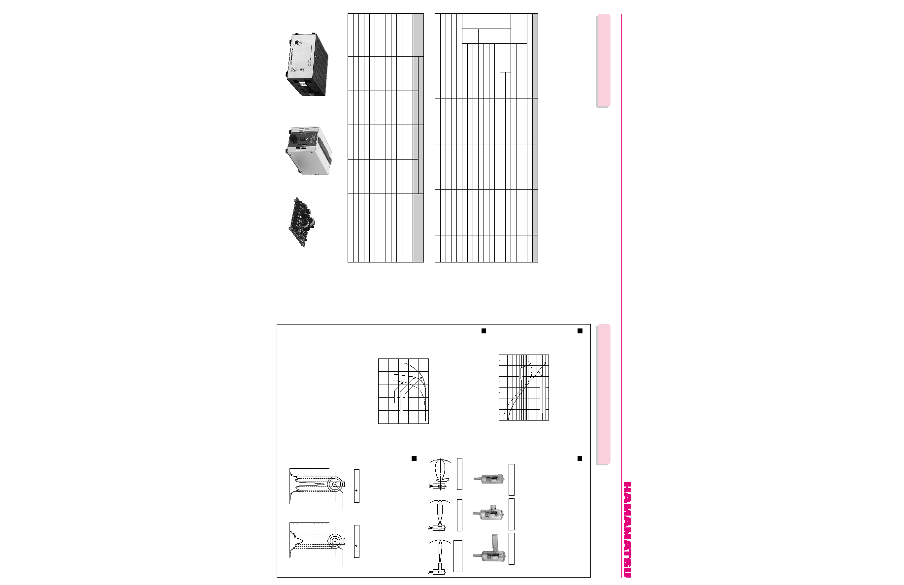
SPECIFICATIONS
L2D2 Lamps
(Deuterium Lamps )
TECHNICAL INFORMATION
The following 4 types of window material are available for deuterium lamps.
(1) UV glass (2) Synthetic silica
(3) MgF
2
Figure 2 shows the transmittance of various window materials.
UV light at wavelengths shorter than 190 nm attenuates greatly due to its
absorption by oxygen. To obtain the fullest performance in window trans-
mittance, it is recommended that the inside of the equipment be filled with
nitrogen or vacuum-evacuated to eliminate this absorption effect.
The non-projecting type uses the side of the cylindrical glass bulb as the
emission window, whilst the projecting type uses a plane glass attached
to a projection on the bulb.
The projecting type has a uniformed transmittance due to the plane glass.
Since the window is located far from the discharge position, the amount
of dirt produced by spattering from the electrodes is reduced resulting in
low deterioration of light output. The non-projecting type requires less
space and has a wider directivity since there is no projection, enabling
effective use of emitted light. The long-nose projecting type uses an
MgF
2
window and is suitable for vacuum ultraviolet applications. This
type is used with the tip of the nose inserted into the vacuum equipment.
Spectral Distribution
Window Material
Figure 1: Spectral Distribution
Figure 2: Typical Transmittance of Various Window Materials
GUV glass
GSynthetic silica
GMgF
2
TLSOB0024ED
Light Distribution
Deuterium lamps emit high intensity light in the UV range at wavelengths
shorter than 400 nm. Light intensity on the short wavelength side is deter-
mined by the window material used.
UV glass has a higher ultraviolet transmittance than normal optical glass
(borosilicate glass). It has the longest cut off wavelength of 185 nm among
the four types. However the generation of ozone is lower than other wind-
ow material types, it is not necessary to have special anti-ozone treat-
ments.
Synthetic silica is obtained by fusing a silica crystal that is artificially
grown. Although its cut off wavelength is 160 nm, it contains less impuri-
ties than fused silica, and transmittance at 200 nm has been improved by
approx. 50 %.
MgF
2
is a crystallized form of alkali metal halide that has an excellent
ultraviolet transmittance, a low deliquescence and is used as window
material for vacuum ultraviolet applications. Its cut off wavelength is 115
nm.
Figure 3: External View
Figure 4: Directivity (Light Distribution)
Non-projecting type
Projecting type
Long-nose projecting type
Non-projecting type
Projecting type
30
∞
15
∞
0
15
∞
30
∞
TLSOB0021EA
30
∞
15
∞
0
15
∞
30
∞
TLSOB0020EA
TLSOB0077EA
Long-nose
Projecting type
TLSOF0139
Figure 5: Arc Distribution
Arc Distribution
0.5 mm
APERTURE
APERTURE:
0.5 mm
1.0 mm
APERTURE
Y
X
Y
X
INTENSITY
INTENSITY
(High Brightness Version)
(Standard Version)
APERTURE:
1.0 mm
TLSOB0049EB
Arc intensity is determined by the aperture (light exit) size. Figure 5
shows typical spectral distributions for lamps with different aperture sizes.
At the same input current and voltage, lamps with an aperture of 0.5 mm
diameter (high brightness type) provide 1.6 times higher brightness than
lamps with an aperture of 1.0 mm diameter (standard type). The half
width of spectral distribution also becomes narrower with a reduced aper-
ture size. When higher intensity is required or the object to be irradiated
is very small, the high brightness type is recommended.
8
HEATER VOLTAGE AND CURRENT
160
200
240
280
320
360
400
WAVELENGTH (nm)
RADIANT INTENSITY (
µ
W/cm
2
∑nm at 30 cm)
0.5
0.1
0.05
0.01
UV GLASS
SYNTHETIC SILICA
(PROJECTING TYPE, 1 mm THICK)
200
250
300
350
150
100
WAVELENGTH (nm)
20
40
60
80
100
TRANSMITTANCE (%)
UV GLASS
SYNTHETIC SILICA
MgF
2
30
∞
10
∞
20
∞
0
10
∞
20
∞
30
∞
C1518
TLSOF0068
TLSOF0150
TLSOF0150
C7860
M7628
7
POWER SUPPLY
Control Methode
Input
Output
Ambient Temperature
Cooling
Dimensions (W
◊ H ◊ D)
Weight
Certification
C1518 (2.5 V)
C1518 (10 V)
C1518 (SQ2.5 V)
C1518 (SQ10 V)
C7860/M7628-2510
C7860/M7628-2517
A
C7860/M7628-3000
A
C7860/M7628-1035
A
C7860/M7628-1070
C7860/M7628-1555
A
NOTE A C7860 series are manufactured only when the order is placed.
* Characteristics are measured at 23
±1 ∞C after 30 min of warming up.
2.5
± 0.2
10
± 1
2.5
± 0.2
10
± 1
2.5
± 0.15
2.5
± 0.15
3
± 0.15
10
± 0.5
10
± 0.5
15
± 0.75
L6565, L7293, L6999, L6999-50
L7307, L7174, L6301, L6302
L6307, L6308, L7292
L7298, L6303, L6304, L7306
L7296, L7295, L6309, L6310, L7296-50
L6565, L7293, L6999, L6999-50
L7307, L7174, L6301, L6302
L7298, L6303, L6304, L7306
L6566, L6305, L6306
L6307, L6308, L7292
L7296, L7295, L6309, L6310, L7296-50
L6311, L6311-50, L6312, L6312-50
Input Voltage
Input Wattage
Output Voltage
Output Current
Trigger Voltage
Fluctuation (p-p)
Drift
Output Voltage
Output Current
Warm-up Time
Dropper Type
(AC) 100/118/230
±10 %
100
(DC) 80
(DC) 160
300
600
± 50
0.1
±0.1
See below
See below
20
0 to +40
Not required
200
◊ 107 ◊ 240
6.7
--
Switching Type
(DC) 24
± 2.4
48
(DC) 80
(DC) 160
300
600
± 50
0.5
±0.1
See below
See below
25
0 to +40
20 CMF of forced air
100
◊ 118 ◊ 36.2
0.17
UL/CE
--
V
VA Max.
V Typ.
V Typ.
mA
V peak
% Max.
%/h Max.
--
--
s Typ.
∞C
--
mm
kg
--
Switching Type
(AC) 90 to 115/180 to 250
(Automatic)
60
(DC) 80
(DC) 160
300
600
± 50
0.5
±0.1
See below
See below
25
0 to +40
Not required
113
◊ 122 ◊ 220
2.7
--
With Load
Without Load
Anode
Heater
Parameter
Type No.
Warm-up
Voltage (V dc)
4
0.8
4
1.2
4
4
5
0.8
1.2
0.5
Current (A dc typ.)
1.0
± 0.1
3.5
± 0.5
1.7
± 0.2
7.0
± 0.5
1
± 0.05
1.7
± 0.1
0
3.5
± 0.2
7
± 0.35
5.5
± 0.3
Operation
Applicable Lamps
Voltage (V dc)
1.8
0.3
3.3
1
1.8
3.3
0
0.3
1
0.3
Current (A dc typ.)
C1518
C7860
M7628
Unit