
L8013 is a high-speed LED developed for optical data links using PCF200 fibers. L8013 uses a non-confined structure chip that does not show
the abrupt deterioration often encountered in some types of confined chips, thus providing high reliability over extended operation time. The
optical output at the fiber end usually tends to vary due to non-uniform LED chip thickness. L8013 minimizes this problem by using a light
condensing reflector with a slight matching offset from the chip. This widens the fiber input beam profile so fine adjustment of the optical axis is
not required.
Features
l Easy optical axis alignment
l High-speed response: 50 MHz Typ.
l High optical output: 45 µW Typ.
(I
F
=30 mA, when used with PCF200 fiber)
l High reliability
Applications
l Optical data link
L E D
Infrared LED
Easy optical axis alignment LED for PCF200 fiber data links
L8013
s Absolute maximum ratings (Ta=25
∞C, unless otherwise noted)
Parameter
Symbol
Condition
Value
Unit
Reverse voltage
V
R
Max.
3
V
Forward current
I
F
80
mA
Forward current decrease rate
-
Ta > 25 ∞C
1
mA/
∞C
Pulse forward current
I
FP
Pulse width=10 µs
Duty ratio=1 %
0.5
A
Pulse forward current
decrease rate
-
Ta > 25 ∞C
6.5
mA/
∞C
Power dissipation
P
150
mW
Operating temperature
Topr
-30 to +85
∞C
Storage temperature
Tstg
-40 to +100
∞C
s Electrical and optical characteristics (Ta=25
∞C)
Parameter
Symbol
Condition
Min.
Typ.
Max.
Unit
Peak emission wavelength
p
I
F
=30 mA
840
870
900
nm
Spectral half width
I
F
=30 mA
-
45
-
nm
Fiber end output *
1
Pf
I
F
=30 mA
30
45
-
µW
Radiant flux
e
I
F
=30 mA
4.5
6.5
-
mW
Forward voltage
V
F
I
F
=30 mA
-
1.45
1.6
V
Reverse current
I
R
V
R
=3 V
-
-
10
µA
Cut-off frequency *
2
fc
I
F
=30 mA ± 4 mAp-p
30
50
-
MHz
*1: PCF200 fiber; distance between fiber end and L8013 cap glass: 0.3 mm
*2: Frequency at which the optical output decreases by -3 dB versus a reference output level at 100 kHz.
1
Infrared LED
L8013
HAMAMATSU PHOTONICS K.K., Solid State Division
1126-1 Ichino-cho, Hamamatsu City, 435-8558 Japan, Telephone: (81) 053-434-3311, Fax: (81) 053-434-5184, http://www.hamamatsu.com
U.S.A.: Hamamatsu Corporation: 360 Foothill Road, P.O.Box 6910, Bridgewater, N.J. 08807-0910, U.S.A., Telephone: (1) 908-231-0960, Fax: (1) 908-231-1218
Germany: Hamamatsu Photonics Deutschland GmbH: Arzbergerstr. 10, D-82211 Herrsching am Ammersee, Germany, Telephone: (49) 08152-3750, Fax: (49) 08152-2658
France: Hamamatsu Photonics France S.A.R.L.: 8, Rue du Saule Trapu, Parc du Moulin de Massy, 91882 Massy Cedex, France, Telephone: 33-(1) 69 53 71 00, Fax: 33-(1) 69 53 71 10
United Kingdom: Hamamatsu Photonics UK Limited: 2 Howard Court, 10 Tewin Road, Welwyn Garden City, Hertfordshire AL7 1BW, United Kingdom, Telephone: (44) 1707-294888, Fax: (44) 1707-325777
North Europe: Hamamatsu Photonics Norden AB: Smidesv‰gen 12, SE-171 41 Solna, Sweden, Telephone: (46) 8-509-031-00, Fax: (46) 8-509-031-01
Italy: Hamamatsu Photonics Italia S.R.L.: Strada della Moia, 1/E, 20020 Arese, (Milano), Italy, Telephone: (39) 02-935-81-733, Fax: (39) 02-935-81-741
Information furnished by HAMAMATSU is believed to be reliable. However, no responsibility is assumed for possible inaccuracies or omissions.
Specifications are subject to change without notice. No patent rights are granted to any of the circuits described herein. ©2002 Hamamatsu Photonics K.K.
Cat. No. KLED1033E01
Jan. 2002 DN
0
-2.0
-1.0
0
1.0
(Typ. Ta=25 ∞C, I
F
=30 mA, PCF200 fiber, Z=0.3 mm)
DISTANCE FROM CAP CENTER X, Y (mm)
RELA
TIVE FIBER END OUTPUT (%)
2.0
20
40
60
80
100
120
Z
Y
X
0
0
0.2
0.4
(Typ. Ta=25 ∞C, I
F
=30 mA, PCF200 fiber, X, Y=0 mm)
DISTANCE BETWEEN FIBER END AND CAP SURFACE Z (mm)
RELA
TIVE FIBER END OUTPUT (%)
0.6
20
40
60
80
120
100
Z
Y
X
-40
-20
0
20
(Typ.)
40
60
80
100
0
40
60
80
100
AMBIENT TEMPERATURE (∞C)
RELATIVE ALLOWABLE FORWARD CURRENT (%)
20
KLEDA0073EA
KLEDB0027EB
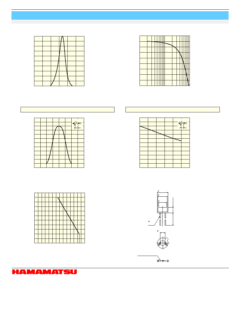
s Dimensional outline (unit: mm)
s Allowable forward current vs. ambient temperature
s Fiber coupling characteristics
s Emission spectrum
X, Y axes
Z axis
s Frequency response
FREQUENCY (MHz)
RELATIVE RADIANT OUTPUT (dB)
-
8
1
10
100
-
5
-
6
-
7
-
1
-
2
-
3
-
4
0
1
(Typ. Ta=25 ∞C, I
F
=30 mA ± 4 mAp-p)
5.4 ± 0.2
4.7 ± 0.15
WINDOW
4.0 ± 0.1
2.7 ± 0.2
13.5 ± 1.0
2.54 ± 0.2
COMMON TO CASE
0.45
LEAD
KLEDB0218EA
KLEDB0219EA
KLEDB0220EA
KLEDB0221EA
700
800
900
1000
0
40
20
60
80
100
WAVELENGTH (nm)
RELATIVE RADIANT OUTPUT (%)
(Typ. Ta=25 ∞C, I
F
=30 mA)
2