 | –≠–ª–µ–∫—Ç—Ä–æ–Ω–Ω—ã–π –∫–æ–º–ø–æ–Ω–µ–Ω—Ç: L8868-02 | –°–∫–∞—á–∞—Ç—å:  PDF PDF  ZIP ZIP |

Left: LC5 series, Right: LC6 series
Brings you "Easy Maintenance" in a "Compact Body".
Delivers new functions for highly advanced optical curing !!
UV SPOT LIGHT SOURCES
NEW
NEW
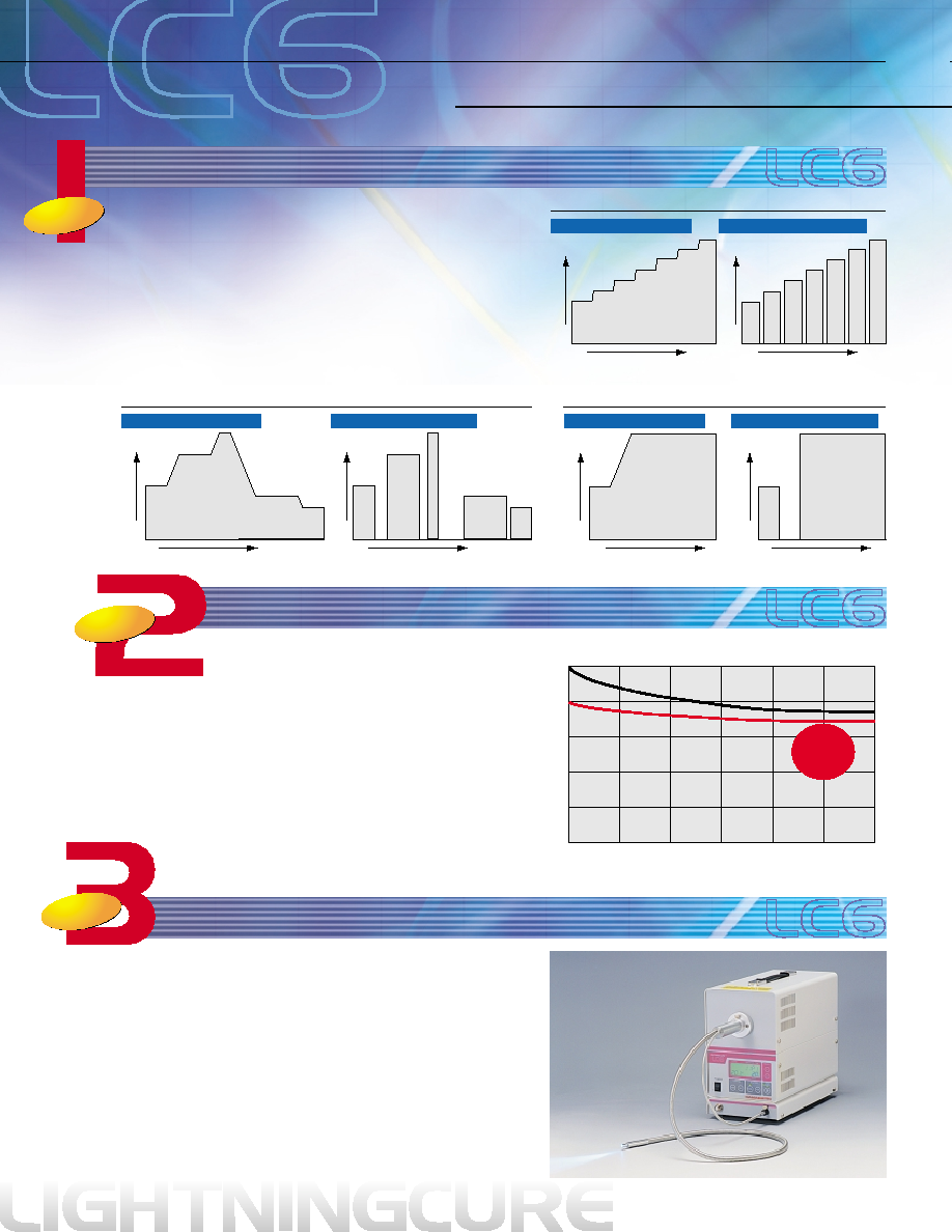
Program example 3: Low light intensity and then long-term high intensity
TIME
TIME
TIME
Program example 1: Increasing light intensity in 7 steps
TIME
LIGHT INTENSITY
LIGHT INTENSITY
LIGHT INTENSITY
LIGHT INTENSITY
LIGHT INTENSITY
LIGHT INTENSITY
TIME
TIME
Program example 2: Random light intensity and irradiation time settings
TLSXB0092EB
RELATIVE LIGHT OUTPUT (%)
OPERATING TIME (h)
500
0
0
40
20
100
80
60
1500
2500
3000
2000
1000
Output
variations
15 %
Stabilized operating mode
Normal operating mode
Light Output Variations
Shutter "open" between steps
Shutter "closed" between steps
Shutter "open" between steps
Shutter "closed" between steps
Shutter "open" between steps
Shutter "closed" between steps
The LC6 now comes loaded with 3 major new functions for better stabilized optical curing
WORLD-WIDE
OPERATION
Memory Step
for 9 types 7-step programs
Stable operating mode available
Program the irradiation intensity and irradiation time to any level you want! Free-
ly set the UV irradiation conditions to match the component you want to bond.
The LIGHTNINGCURE LC6 lets you store nine types of 7-step programs in the
memory, so optimal irradiation conditions matching the component for bonding
can be set just by changing the program number. This holds true even when
multiple bonding components are flowing in the same production process or
when shifting to different production lines.
The LC6 is especially ideal for components that must be fixed in place with
high precision. The mounting positions of these components often deviate due
to stress warping and contraction in the adhesive that causes positional shifts.
Using the LC6 gives better production stability and higher product yield espe-
cially for components demanding high position precision.
Optical power monitor with optical feedback
(option: sold separately)
You can now select stable operating modes to re-
duce variations in light output over elapsed time
while also lowering power consumption about 10
percent compared to standard operation.
Variations in light output can be reduced about 15
percent over 3,000 hours. This means you get stable
light output all the way to the final lamp life stage.
This operating switch is on the surface of rear panel.
An optical power monitor with optical feedback can be added as a
useful option for maintaining constant irradiation power. The built-in
sensor constantly monitors the light intensity that usually varies with
operating time, and the sensor output is feedback to control the iris
so the light intensity is always maintained at a preset constant level.
The irradiation power (reference value) when using the standard
light guide is shown in a digital display (in watts) on an LCD panel.
This eliminates mistakes that occur due to using the wrong condi-
tions or human errors during measurement.
This also means finer control on fully automated lines.
New
Function
New
Function
New
Function

Output intensity vs. panel display
The LC5 brings you easy maintenance in a compact size.
FEATURES & FUNCTIONS
Clever layout allows a compact body
The smallest size (volume) in its product class* compared to previ-
ous products including those made by other manufacturers. Weight
has been also reduced 6.5 kg making it 1.5 kg lighter than previous
other models. Superior product features have all been condensed
into this new, compact body.
*For light sources using lamps rated at 200 W or more.
Anybody can use it! One-touch replacement!
Lamp is replaceable in less than 30 seconds!
Just insert the lamp to replace it. No wiring to worry about. This is
so easy you can do it with one hand.
Lamp is the cassette type with a preset optical axis so no trouble-
some optical alignment is needed after replacement.
* The L8388 and L8878 are exclusively for previous cassette type lamps.
These are replaced the same way as our previous lamp models.
Light intensity adjustable anywhere within 0 to 100%!
Selectable positions of light guide port
Full line-up of external control equipment
(D-sub connector: standard feature, terminal block: option [sold separately])
Power supply compatible
in world-wide
An electric diaphragm mechanism allows a digital display of the rel-
ative light output from 0 to 100% on the LCD panel. Unlike conven-
tional analog scales, this means highly precise light irradiation. Light
output also can be controlled from an external device, so meeting
various kinds of measurement conditions is now even easier.
A front port type and a rear port type are available. The front port
type allows lamp replacement from the operation panel side. This
helps hold limits on equipment movement and installation location
to a minimum.
Select the light guide port position that best matches the compo-
nent for bonding and its mounting position.
Left: Front light guide port type, Right: Rear light guide port type
Internal power supply automatically switches to a 100 or 200 V input.
There is no problem when shifting the operating location in world-
wide.
Turning the lamp on and off and open-
ing-closing of the shutter can be control-
led by input of external signals. An alarm
signal output is also provided. This
means ideal usage conditions on semi or
fully automated production lines.
Restores operation in about 10 seconds after power outages of a
second or less.
Conventional products take at least a few minutes to start up again
after a power shutdown, so you can see this function drastically
shrinks down-time due to power outages.
This function is especially convenient in places where the supply of
power is intermittent or unstable.
Our 200 W lamps have high intensity equal to lamps in the 250 W
class. Light sources using our 200 W lamps also have less power
consumption than those using 250 W lamps.
Power consumption is the lowest in its class (within 300 VA). This
means using multiple UV light source units at production facilities
will yield tremendous energy saving benefits.
Instantaneous power-outage response program
Great energy saving benefits
WORLD-WIDE
OPERATION
Our previous model
180
◊ 290 ◊ 390
Unit: mm
160
◊ 227 ◊ 311
Size Comparison
SERIES
100
90
80
70
60
50
40
30
0
10
20
30
40
50
PANEL DISPLAY (%)
60
70
80
90
100
20
10
0
OUTPUT INTENSITY (%)
UV spot light source: LC5 series
Light guide: A2873 ( 5 mm fiber diameter, 1 mm length)
Output intensity
The LC5 brings you easy maintenance in a compact size.
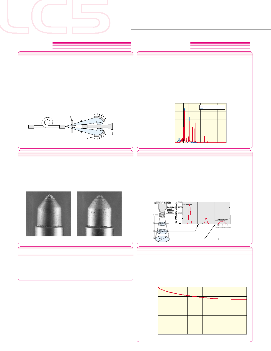
GUV intensity distribution
GStructural View
The LC5 yields an extremely strong spectral distribution in the UV
range most effective for UV curing. UV intensity distribution is de-
pendent on the distance from the light guide output end to the target
surface to be irradiated, as well as on the type of light guide used.
The greater the distance from the light guide output end to the tar-
get surface, the more the maximum UV intensity drops and the
more the light beam expands (see below).
UV intensity: 3500 mW/cm
2
(-01 type, at 365 nm)
TLSXB0095EC
10
20
30
Quartz light guide
10
10
0
10
10
0
0
1000
2000
3000
4000
Distance from radiated center (mm)
UV wavelength: 365 nm
Reference values for this data were taken
using the LC5 UV Spot Light Source
and the A2873 quartz light guide
( 5 mm diameter, 1 meter length).
0
4000
1000
1070 mW/cm
2
3500 mW/cm
2
Long service life
Guaranteed service life: 2000 h, Lamp operating life: 3000 h
UV intensity generally declines with lamp operating time. Hamamatsu
has drastically improved these drops in light intensity by using a
mercury-xenon lamp whose electrodes suffer almost no wear and
an improved optical system.
GVariations in UV intensity [365 nm] over time (typical values)
RELATIVE LIGHT OUTPUT (%)
OPERATING TIME (h)
500
0
0
40
20
100
80
60
1500
2500
3000
2000
1000
TLSXB0092EB
Highly durable shutter
The stepping motor used for the shutter in the LC5 has a service
life 5 times longer than conventional rotary solenoids. Along with
eliminating shutter troubles, the once noisy sound of shutter open-
ing and closing can now hardly be heard. This makes the LC5 ideal
for 24-hour continuous operation.
No optical axis alignment
Uses a highly stable mercury-xenon lamp* developed expressly for
analysis and measurement applications. There is almost no wear
on the electrodes and no positional shift of the arc point.
Absolutely no optical axis alignment is needed, even during lamp
replacement or during lamp use.
GElectrode wear
Before use
After 2000 hours of use
The LC5 combines a mercury-xenon lamp having high-intensity
UV line spectra with an elliptical reflector (UV cold mirror) having
reflectivity higher than 90% in the UV range and a quartz light
guide with excellent UV transmittance.
The lamp can be operated in a horizontal position, so the optical
system has less light loss compared to lamps operated in an up-
right position, allowing the UV light to input efficiently to the light
guide. The elliptical reflector efficiently reflects only the UV light,
and lets heat rays and visible light pass through to prevent adverse
effects from heat on the irradiated point.
High efficiency optical system - no heat problems
Selectable wavelength
The LC5 allows you to select the wavelength range you need. The
"-01" type suitable for wavelengths around 365 nm and the "-02"
type enhanced for 250 nm band are provided. Select the light source
that matches the adhesive agent you use.
These can also be combined with UV-transmitting filters that cut visible
and infrared light, and minimize heat effects on the irradiated point.
A visible light type is also available (radiant wavelength range from
400 nm to 700 nm).
GRadiant spectral distribution
RADIANT INTENSITY (%)
WAVELENGTH (nm)
300
200
0
40
20
100
80
60
500
700
800
600
400
365 nm type [--01]
250 nm enhanced type [-02]
TLSXB0079EB
TLSXC0040EA
Visible light
Heat rays
UV light
Cassette type
lamp
Filter (sold separately)
Light guide
(sold separately)
Elliptical reflector
(UV cold mirror)
* Patented
STRUCTURE
CHARACTERISTICS
High output
NOTE:
SPECIFICATIONS
Parameter
LC5 Series
L8333
L8388
L8222
Operation panel
(front)
Rear
Operation panel
(front)
Top
L6721
L6722
D
L6723
E
Rear
Operation panel
(front)
Light Guide Port
Lamp Replacement Position
UV Intensity
A
Radiant Wavelength Range
B
Lamp for Maintenance
C
Lamp Service Life
Power Supply Input
Power Consumption
Weight
-01
-02
-03
-01
-02
-03
LC6 Series
L8868
L8878
L8858
Operation panel
(front)
Rear
L8251
L8252
D
L8253
E
L8251
L8252
D
L8253
E
3500 mW/cm
2
Typ. (at 365 nm, -01 type)
[365 nm type] 300 nm to 450 nm
[250 nm band enhanced type] 240 nm to 400 nm
[Visible light type] 400 nm to 700 nm
Guaranteed life 2000 h, Lamp operating life 3000 h
100 V ac to 240 V ac (100 V / 200 V auto switching), single phase 47 Hz to 63 Hz
300 VA Max.
Approx. 6.5 kg
Operation panel
(front)
Top
L6721
L6722
D
L6723
E
Rear
Operation panel
(front)
*
1
10P terminal block is available as option (sold separately).
*
2
Corresponds to "start/stop" of Memory Step
for the LC6.
*
3
These functions are available only for the LC6.
K : available, -- : not available
K : available, -- : not available
Control
Main Power ON/OFF
Lamp ON/OFF
Shutter Drive
Irradiation Program (Memory Step
) Setting *
3
Optical Power Adjustment (UP/DOWN)
Lamp ON Indicator
Lamp Stability Indicator
Shutter Open Indicator
Lamp Operation Hour Meter
Overheat Alarm
Lamp Operation Time Alarm
Open/Close
Auto Open/Close by Timer *
2
Auto Shutter Time Setting
LC6 Series ∑ LC5 Series
External control terminal
(D-SUB connector) *
1
Front panel operation
--
K
K
K
--
--
K
K (Signal Output)
K (Signal Output)
K (Signal Output)
--
K (Signal Output)
K (Signal Output)
K
K
K
K
K
K
K
K
K
K
K
K
K
LC5 series
L8333
L8388
L8222
K
--
--
--
--
K
LC6 Series
L8868
L8878
L8858
K
K
K
(Option: sold separately)
--
K
Functions
One-touch Lamp Replacement
Irradiation Program (Memory Step
)
Stabilized Operation Mode
Optical Power Monitor with Optical Feedback
A UV irradiance (at 365 nm) is measured in the center at a point 10 mm away from the output end of the A2873 light guide (sold separately), by using the Hamamatsu
C6080-13 UV power meter.
B Major radiant wavelengths. Various optical filters (sold separately) can also be attached.
C L8251 and L6721 are 200 W super-quiet mercury-xenon lamps with ozone-free bulb. L8252 and L6722 are 200 W super-quiet mercury-xenon lamps. L8253 and
L6723 are 150 W super-quiet xenon lamps with ozone-free bulb.
D Ozone-free type is also available.
E Standard quartz type is also provided.
FUNCTIONS
CONTROL

L8858 / L8222
L8868 / L8333
[TOP VIEW]
[SIDE VIEW]
[REAR VIEW]
[FRONT VIEW]
160
311
12
8
21
8.5
LAMP
REPLACEMENT
PORT
LIGHT GUIDE
CONNECTOR
EXTERNAL
CONTROL
TERMINALS
OPERATION PANEL
157
227
AC INPUT CONNECTOR
(FUSE HOLDER)
STABLE OPERATING MODE SWITCH
FOR ONLY LC6
COOLING FAN
DIMENSIONAL OUTLINES
311
12
8
21
8.5
[TOP VIEW]
[SIDE VIEW]
[FRONT VIEW]
OPERATION PANEL
[REAR VIEW]
160
CONTROL
TERMINALS
LIGHT GUIDE
CONNECTOR
227
157
LAMP
REPLACEMENT
PORT
AC INPUT CONNECTOR
(FUSE HOLDER)
STABLE OPERATING MODE SWITCH
FOR ONLY LC6
COOLING FAN
(Unit: mm)
(Unit: mm)

WARNING
WARRANTY PERIOD
G Light
This equipment emits very strong ultraviolet light which is harmful to eyes and the skin.
Also, as the light emanating from the light guide connection aperture contains infrared light in addition to ultraviolet light,
its irradiation will cause heat generation.
Be sure to observe following instructions for operation of the equipment.
∑ Never look directly into the light guide connection aperture or at the light emanating from the light guide. Strong ultravio-
let light can cause visual disorder.
∑ Do not allow light to come into contact with skin. Contact with skin may cause sunburn-grade inflammation. Always
wear safety glasses, gloves, and other appropriate protective gear when operating this equipment.
∑ Never allow light from the light guide to radiate onto flammable material.
∑ The unit includes an interlock that prevents the lamp from lighting while to top cover is open. Never attempt to override
the interlock function by manually depressing the switch, as this may result in uncontrolled release of dangerous ultra-
violet light.
G High-Voltage trigger
∑ The mercury-xenon lamp employed started by a high-voltage (30 kV) pulse applied at the lamp electrodes.
As protection against accidental electrical shock hazard, the design includes an interlock switch that disables lamp op-
eration while the top cover is open.
Never attempt to turn on the lamp by blocking the sensor window of the interlock switch.
G Lamp Replacement
∑ The inside of the lamp housing becomes extremely hot during lamp operation.
Before replacing the lamp, switch it off and run the cooling fan for at least 15 minutes.
∑ Always exercise due caution when handling or replacing a lamp.
A lamp contains high-pressure gas [approximately 1 MPa (10 atmospheres) at room temperature, approximately 4 MPa
(40 atmospheres) during operation] and may burst if dropped or otherwise impacted.
G Inhibition of Removal and Modification
∑ Do not remove the top cover or under cover unless absolutely necessary and never touch any of the screws inside the
unit. As the internal components of this unit have been precisely adjusted, disassembling or modifying the equipment
can cause problems with the unit, fire and electrical shock.
This device is guaranteed for one year after delivery date from us. The warranty extends only to replacement of the prod-
ucts. The warranty does not cover damage due to misuse or natural calamity.

TLSX1036E02
MAR. 2002 IP
(2000)
HAMAMATSU PHOTONICS K.K., Electron Tube Center
314-5, Shimokanzo, Toyooka-village, Iwata-gun, Shizuoka-ken, 438-0193, Japan, Telephone: (81)539/62-5248, Fax: (81)539/62-2205
U.S.A.: Hamamatsu Corporation: 360 Foothill Road, P. O. Box 6910, Bridgewater. N.J. 08807-0910, U.S.A., Telephone: (1)908-231-0960, Fax: (1)908-231-1218 E-mail: usa@hamamatsu.com
Germany: Hamamatsu Photonics Deutschland GmbH: Arzbergerstr. 10, D-82211 Herrsching am Ammersee, Germany, Telephone: (49)8152-375-0, Fax: (49)8152-2658 E-mail: info@hamamatsu.de
France: Hamamatsu Photonics France S.A.R.L.: 8, Rue du Saule Trapu, Parc du Moulin de Massy, 91882 Massy Cedex, France, Telephone: (33)1 69 53 71 00, Fax: (33)1 69 53 71 10 E-mail: infos@hamamatsu.fr
United Kingdom: Hamamatsu Photonics UK Limited: 2 Howard Court, 10 Tewin Road Welwyn Garden City Hertfordshire AL7 1BW, United Kingdom, Telephone: 44-(0)1707-294888, Fax: 44(0)1707-325777 E-mail: info@hamamatsu.co.uk
North Europe: Hamamatsu Photonics Norden AB: Smidesv‰gen 12, SE-171-41 SOLNA, Sweden, Telephone: (46)8-509-031-00, Fax: (46)8-509-031-01 E-mail: info@hamamatsu.se
Italy: Hamamatsu Photonics Italia: S.R.L.: Strada della Moia, 1/E, 20020 Arese, (Milano), Italy, Telephone: (39)02-935 81 733, Fax: (39)02-935 81 741 E-mail: info@hamamatsu.it
HOMEPAGE URL http://www.hamamatsu.com
[CONSULT US ABOUT UV CURING OR ANY RELATED ITEM]
RELATED PRODUCTS
UV POWER METER C6080 Series
The C6080 series is a UV power meter
specifically designed to measure the in-
tensity of UV radiation. Its compact size
and simple operation are ideal for rou-
tine UV control work.
UV BONDING EQUIPMENT
We design and configure simple UV cur-
ing or bonding equipment combined with
dispensers and other devices.
We also welcome your queries regarding
adhesive, bonding agents and syringes.
Feel free to contact our sales office.
We are available to help answer your various questions or concerns about UV curing or bonding.
We can provide the ideal combination of UV adhesive to meet your particular needs for bonding strength or job speed, etc.
∑ Various light guides
In addition to multi-furcated light guides, Hamamatsu pro-
vides light guide with various exit shapes such as linear
(slit) type, square type, round type and special shapes to
meet your specific needs.
Condenser lenses, protective glasses and others.
* A catalog listing these accessories are available. Please ask our sales office for your
free copy.
ACCESSORIES FOR UV SPOT LIGHT SOURCES
∑ UV-transmitting filters
These filters transmit UV light while
cutting visible and infrared light so heat
generation on the irradiated point can
be minimized. Effective in bonding
parts vulnerable to heat.
TEMPERA
TURE ON IRRADIA
TED SURF
A
C
E (
∞
C)
IRRADIATION TIME (s)
250
200
150
100
50
0
0
60
50
40
30
20
10
Without filter
With filter 1
With filter 2
Temperature changes on irradiated surface
∑ Irradiated object: Glass epoxy board
∑ Irradiation distance: 10 mm
∑ Light source: LC5
∑ Light guide: A2873
TLSOXB0100EB
Information furnished by HAMAMATSU is believed to be reliable. However, no responsibility is assumed for possible inaccuracies or omissions. Specifications are
subject to change without notice. No patent rights are granted to any of the circuits described herein. ©2002 Hamamatsu Photonics K.K.
Subject to local technical requirements and regulations, availability of products included in this promotional material may vary. Please consult with our sales office.
ROOM TEMPERATURE
ISO9001 Certification
JQA-1574
UV SPOT LIGHT SOURCES
This product(s) conforms to
the EMC directive/ EN61326:1997 +
A1:1998 class A and
the LVD/ EN61010-1:1993 + A2:1995
of the European Union.