 | –≠–ª–µ–∫—Ç—Ä–æ–Ω–Ω—ã–π –∫–æ–º–ø–æ–Ω–µ–Ω—Ç: R2487 | –°–∫–∞—á–∞—Ç—å:  PDF PDF  ZIP ZIP |
1
Information furnished by HA MAM ATS U is believed to be reliable. However, no responsibility is assumed for possible inaccuracies or omissions. Specifications are
subject to change without notice. No patent rights are granted to any of the circuits described herein.
©
1998 Hamamatsu Photonics K.K.
Subject to local technical requirements and regulations, availability of products included in this promotional material may var y. Please consult with our sales office.
POSITION-SENSITIVE
PHOTOMULTIPLIER TUBES
WITH CROSSED WIRE ANODES
R2487 SERIES
3 x 3 Square Envelope Position-Sensitive PMT with Crossed Wire Anodes
For Nuclear Medical Instrument, High Energy Physics Experiments
Introduction
The R2487 series have a bialkali photocathode, a 12-stage
coarse mesh dynode structure, and multiple anode wires
crossing one another in the X and Y directions. Output
signals from each anode are divided through external re-
sistive chains and derived from X and Y electrodes as the
position signals. This crossed-wire anode construction
features high spatial resolution, high position linearity, and
easy signal processing for scintillation imaging.
The R2487 series are new photomultiplier
tubes which enable the acquisition of 2-di-
mensional information from a single tube.
Until now, the task of obtaining 2-dimensional information
required the use of an arrangement of multiple PMTs. This
approach was costly and required complex hardware. The
R2487 series were developed as position-sensitive PMTs
to enable this information acquisition with a single tube.
Potential applications span a wide range of
imaging fields
The R2487 series use a mesh-dynode with excellent lin-
earity and position-sensitive crossed wire anodes, enabling
detection and imaging of a wide variety of emission phe-
nomena.
Applications
∑
Radiology: compact scintillation cameras, positron CTs
∑
High-energy physics
∑
Astronomy: sensing and imaging of cosmic radiation
∑
Chemical analysis, materials research, life sciences
Voltage divider circuit and resistive chains
for signal processing simplify connection to
measuring instruments.
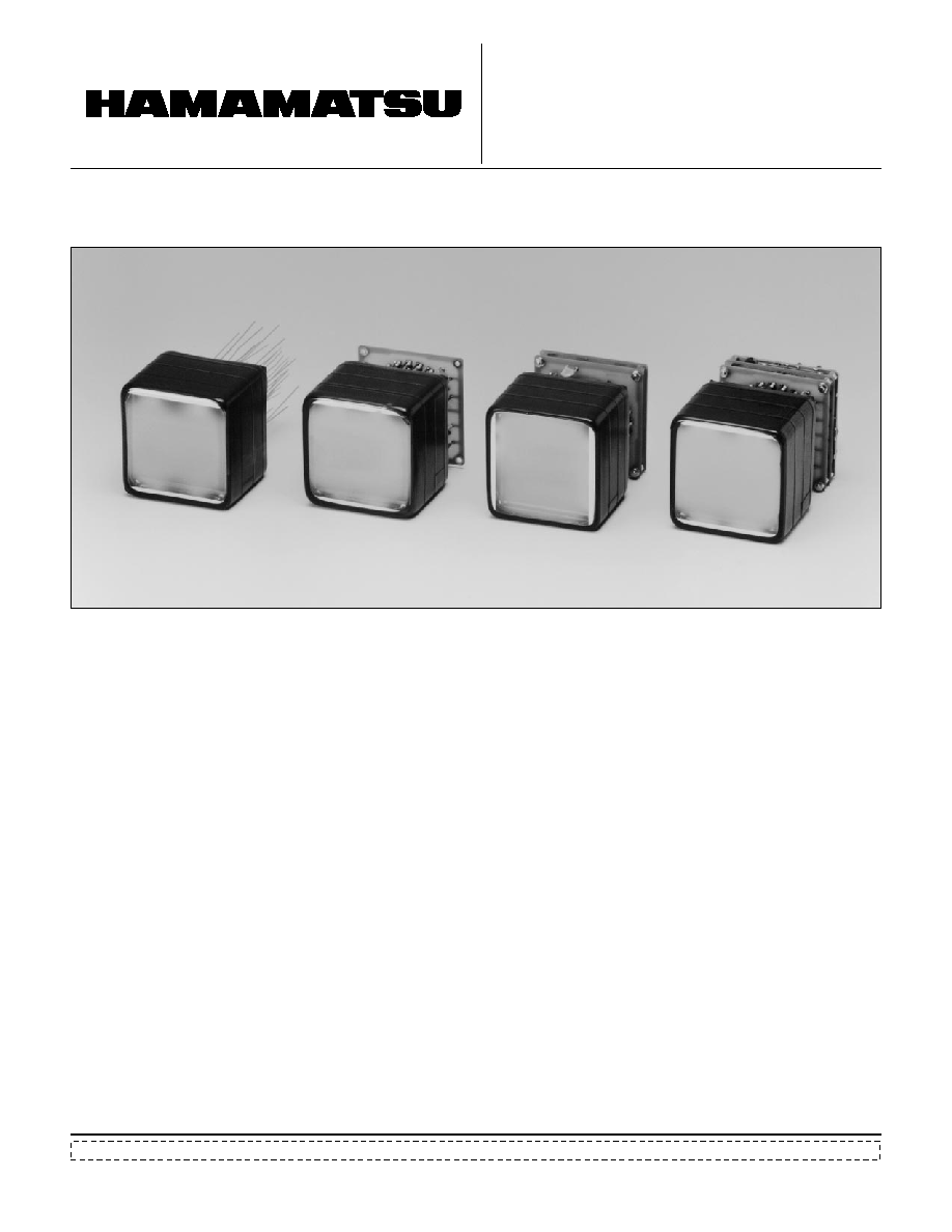
The following versions are avaliable to handle various ap-
plications.
1. R2487:
Flying lead type (Fig. 7)
2. R2487-01: Provided with high-voltage divider circuit; enables direct
reading of signals from each anode through an IC socket.
(Fig. 8)
3. R2487-02: Provided with high-voltage divider circuit and resistive
chains for signal processing, simplifying connection to
external devices. (Fig. 9)
4. R2487-05: With Pre-Amp of -02 (Fig.10)
TPMHF0049
POSITION-SENSITIVE PHOTOMULTIPLIER TUBES R2487 SERIES
2
NOTES
: Averaged over any interval of 30 seconds maxi-
mum.
: The light source is a tungsten filament lamp op-
erated at a distribution temperature of 2856K.
Supply voltage is 150 volts between the cathode
and all other electrodes connected together as
an anode.
: The value is cathode output current when a blue
filter (Corning CS No. 5-58 polished to 1/2 stock
thickness) is interposed between the light source
and the tube under the same condition as Note
.
: Measured with the same light source as Note
and with the anode-to-cathode supply voltage and
voltage distribution ratio shown in Table 1.
: Measured with the same supply voltage and volt-
age distribution ratio as Note at 30 minutes after
removal of light.
: The rise time is the time for the output pulse to
rise from 10% to 90% of the peak amplitude
when the entire photocathode is illuminated by
a delta function light pulse.
: The electron transit time is the interval between
the arrival of a delta function light pulse at the
entrance window of the tube and the time the
output pulse reaches the peak amplitude. In
measurement the entire photocathode is illumi-
nated.
X
B
X
A
Y
D
Y
C
GND
-HV
K
PHOTOMULTIPLIER
TUBE
Dy
1
Dy
2
Dy
11
Dy
12
CROSSED
WIRE ANODES
(X
A
- X
B
)
ADDITION/
SUBTRACTION
X ADDRESS
Y ADDRESS
EVENT
SIGNAL
(X
A
+ X
B
)
(X
A
+ X
B
+
Y
C
+ Y
D
)
(Y
C
- Y
D
)
(Y
C
+ Y
D
)
DIVISION
A/D
WINDOW
DIVISION
A/D
X
A
PREAMPLIFIER
INTEGRATION
X
B
Y
C
Y
D
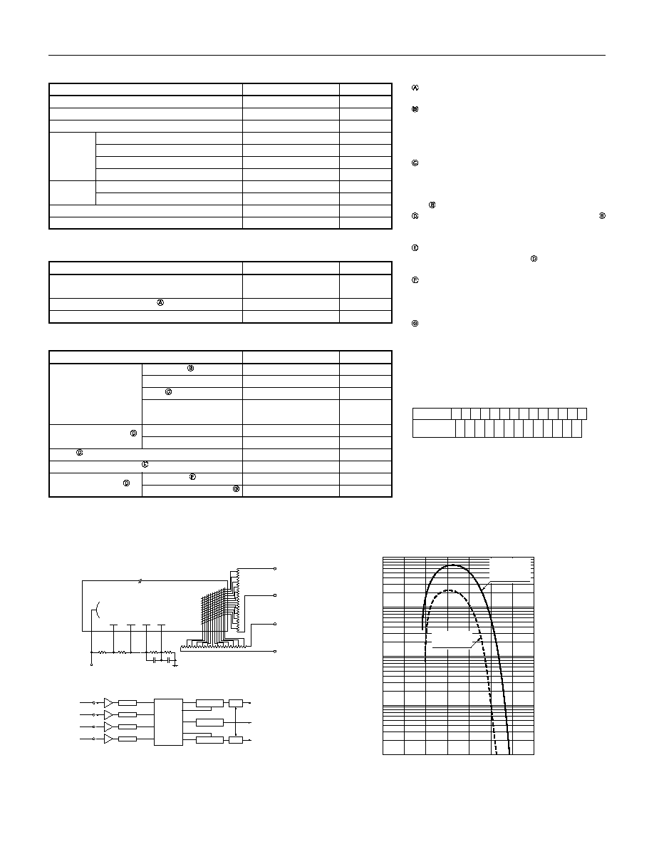
Figure 1: Schematic Diagram
TPMHC0154EA
Figure 2: Typical Spectral Response
200
800
600
400
0.01
0.1
1
10
100
CATHODE RADIANT SENSITIVITY (mA / W)
QUANTUM EFFICIENCY (%)
WAVELENGTH (nm)
CATHODE
RADIANT
SENSITIVITY
QUANTUM
EFFICIENCY
TPMHB0495EA
Table 1: Voltage Distribution Ratio and Supply Voltage
Electrode
K D
1
D
2
D
3
D
4
D
5
D
6
D
7
D
8
D
9
D
10
D
11
D
12
P
Distribution
Ratio
Supply Voltage: 1250 Vdc
K: Cathode, D: Dynode, P: Anode
1
1
1
1
1
1
1
1
1
1
1
1
1
Parameter
GENERAL
Spectral Response
Wavelength of Maximum Response
Photocathode Material
Window
Dynode
Anode Number of Wires
Effective Area
300 to 600
420
Bialkali
Borosilicate glass
Plano-plano
3.2
±
0.3
1.500
±
0.001
Coarse mesh
12
18 (X) + 16 (Y)
55 (X)
◊
55 (Y)
nm
nm
--
--
mm
--
--
--
--
--
mm Min.
Material
Shape
Thickness
Index of Refraction at 420nm
Structure
Number of Stages
Description/Value
Unit
Parameter
CHARACTERISTICS (Typ. at 25
∞
C)
Cathode Sensitivity
Anode Sensitivity
Gain
Anode Dark Current
Time Response
80
77
9.0
23
8.0
7.7
◊
10
3
1.0
◊
10
5
20
5.5
17
µ
A/lm
mA/W
µ
A/lm-b
%
A/lm
A/W
--
nA
ns
ns
Luminous
Radiant at 420nm
Blue
Quantum Efficiency
at 390nm (peak)
Luminous
Radiant at 420nm
Rise Time
Electron Transit Time
Value
Unit
Parameter
MAXIMUM RATINGS (Absolute Maximum Values)
Supply Voltage
Between Anode and Cathode
Average Anode Current
Ambient Temperature
1300
0.1
-80 to +50
Vdc
mA
∞
C
Value
Unit
3
1.0
0.8
0.2
0.1
0.4
0.6
10
2
10
3
10
4
10
5
SPATIAL RESOLUTION (FWHM)
NUMBER OF INCIDENT PHOTONS (photons/event)
(mm)
SPOT SIZE=1.0 mm DIA.
WAVELENGTH=565 nm
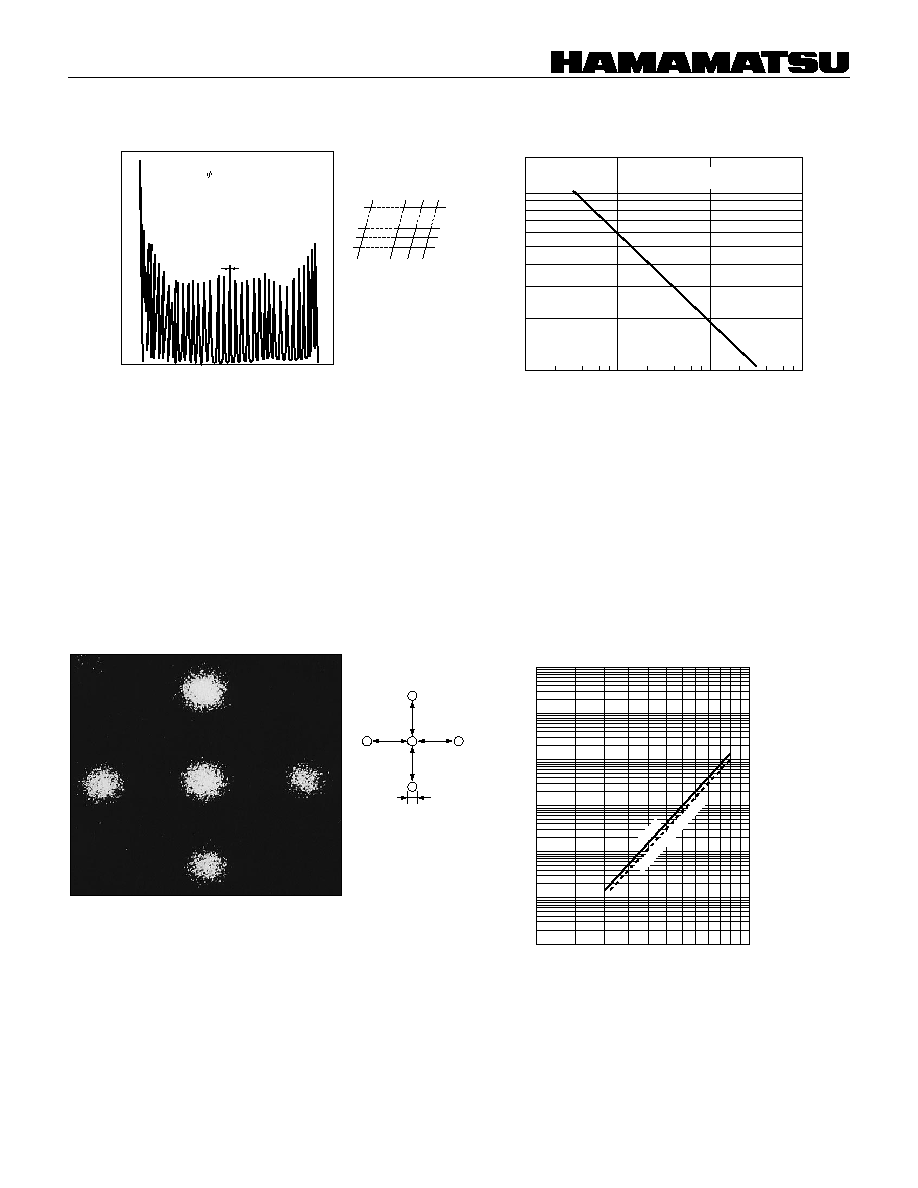
Figure 3: Example of Spatial Resolution
Figure 4: Example of Spatial Resolution
as a Function of Incident Photons
TPMHB0447EA
TPMHB0150EB
NOTE:
Measurement should be done by projecting spotlights of
1 mm with an interval of 1 mm, and inputting the position
operation output into the Pulse Height Analyzer. Fluctua-
tion of the position signal (FWHM = 0.3 mm) shows the
limit of the spatial resolution.
Figure 5: Example of Scintillation Imaging
Figure 6: Typical Anode Sensitivity and Gain
Characteristics
Position of Incident Radiation
500
300
700
1000
1500
10
7
10
6
10
5
10
4
10
3
10
2
10
1
10
3
10
2
10
1
10
0
10
-1
10
-2
10
-3
SUPPLY VOLTAGE (V)
GAIN
ANODE SENSITIVITY (A/lm)
ANODE SENSITIVITY
GAIN
TPMHB0482EA
TPMHF0062
CHANNEL NUMBER
FWHM=0.3mm
COUNT PER CHANNEL
SUPPLY VOLTAGE=1250V
SPOT SIZE= 1.0 mm
SPOT INTERVAL=1.0 mm on PHOTOCATHODE
NUMBER OF INCIDENT PHOTONS=4000 per EVENT
2 mm
10 mm
10 mm
NaI (TI): 5 mmt +
57
Co
Supply Voltage = 1250 V
ANODE
PITCH=X direction: 3.75 mm
Y direction: 3.7 mm
NUMBER= 18+16
(X) (Y)
POSITION-SENSITIVE PHOTOMULTIPLIER TUBES R2487 SERIES
4
R2487-05
ORTEC 460
X
A
X
B
Y
C
Y
D
Y
C
+ Y
D
X
A
+ X
B
X
A
X
A
+ X
B
DELAY
LINE
AMP.
SUMMING
AMP.
ORTEC 533
POSITION
INPUT
POSITION SENSITIVE
DETECTOR ANALYZER
ORTEC 464
OSCILLOSCOPE
A/D CONVERTER
etc.
X
POSITION
Y
POSITION
X
Y
ENERGY
INPUT
POSITION
INPUT
ENERGY
INPUT
Y
C
Y
C
+ Y
D
CAMERA
R2487-05
OSCILLO-
SCOPE
POSITION
ANALYZER
C4065
HAMAMATSU
DATA PROCESSOR
C4095-10
X
Y
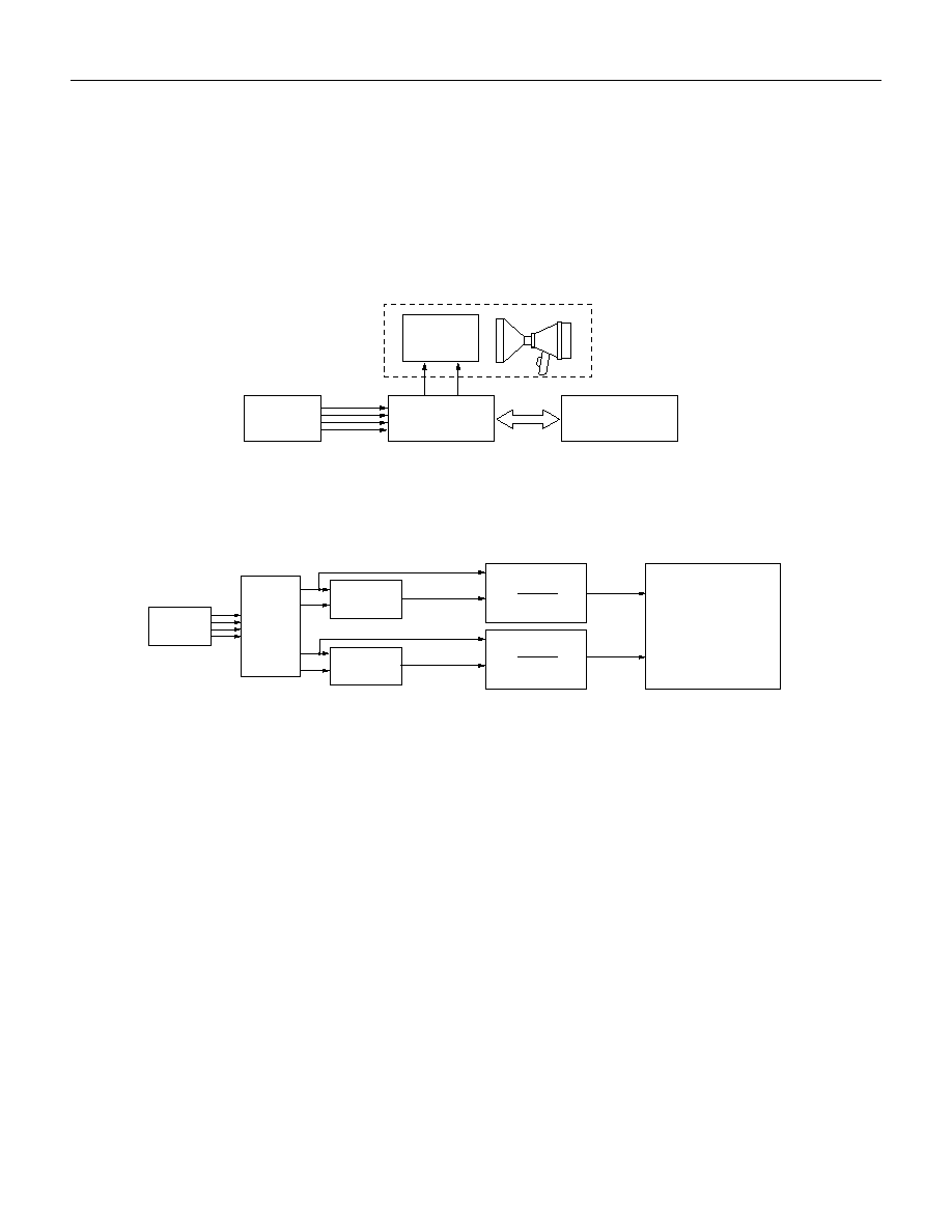
OPERATING EXAMPLE
The R2487-05 can be connected commercially available general-purpose measuring instruments. The figures below
show a typical connection example.
1. In this setup, the R2487-05 is connected to the Hamamatsu C4065 Position Analyzer, with both analog and digital
outputs avalable.
2. Owners of Ortec Position-Sensitive Detector Analyzer (NIM Module) can also connect to this device.
TPMHC0157EA
TPMHC0158EA
5
(TOP VIEW)
Anode Pitch
X drection: 3.75mm
Y drection: 3.7mm
(BOTTOM VIEW)
SEMI FLEXIBLE LEADS
PHOTO-
CATHODE
HA
COATING
78
±
1
◊
78
±
1
55(X)
◊
55(Y) MIN.
40.0
±
0.5
54.0
±
0.5
70
±
2
DY
4
DY
8
DY
10
DY
12
DY
11
DY
9
DY
7
DY
3
DY
1
DY
2
K
FOCUS
Y1
Y2
Y3
Y4
Y5
Y13
Y14
Y15
Y16
X
18
X
17
X
16
X
5
X
1
X
4
X
3
X
2
DY
5
DY
6
X5
X4
X3
X2
X1
Y9
Y8
Y8
Y8
Y7
Y5
Y3
Y1
X18
X17
X16
X15
X14
X13
X12
X10
Y9
X11
Y10
Y11
Y12
Y13
Y14
Y15
Y16
X8
X7
X6
X9
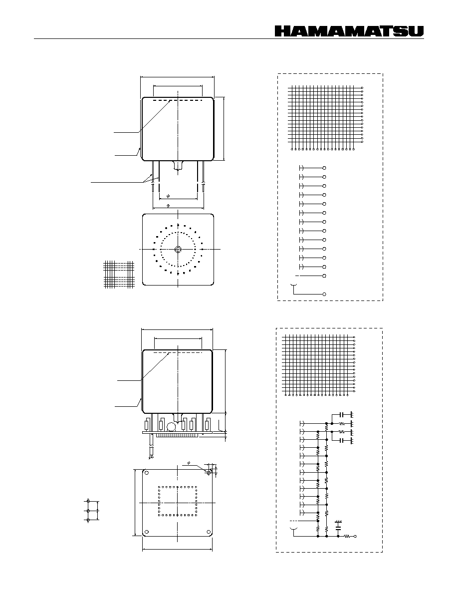
DIMENSIONAL OUTLINE (Unit: mm)
Figure 7: R2487
Figure 8: R2487-01
TPMHC0172EA
(BOTTOM VIEW)
EMC 14120-01-445
IC SOCET (SNAP SIP)
PHOTO-
CATHODE
IC SOCKET PITCH
78
±
1
◊
78
±
1
70
±
2
20
±
1
1.6
4
2- 3.2
2.54
2.54
Y
5
X
14
X
13
X
12
X
11
Y
1
Y
2
Y
3
Y
4
55(X)
◊
55(Y) MIN.
X
10
X
4
X
3
X
2
Y
8
Y
9
Y
7
Y
6
X
1
Y
14
Y
13
Y
12
X
18
Y
10
X
17
X
16
X
15
Y
11
X
8
X
9
X
7
Y
15
Y
16
X
6
X
5
74
74
3.8
3.8
HA
COATING
TPMHC0173EA
TPMHA0427EA
Y16
Y15
Y14
Y13
Y12
Y11
Y10
Y9
Y8
Y7
Y6
Y5
Y4
Y3
Y2
Y1
X16
X15
X18
X17
X14
X13
X12
X11
X10
X9
X8
X7
X6
X5
X4
X3
X2
X1
K
FOCUS
DY
12
DY
11
DY
10
DY
9
DY
8
DY
7
DY
6
DY
5
DY
4
DY
3
DY
2
DY
1
K
DY
12
DY
11
DY
10
DY
9
DY
8
DY
7
DY
6
DY
5
DY
4
DY
3
DY
1
FOCUS
2R
1R
2R
2R
2R
2R
2R
2R 1R
2R
1R
C
2
C
1
C
3
2R
2R
2R
2R
1R
-HV
100K
Y16
Y15
Y14
Y13
Y12
Y11
Y10
Y9
Y8
Y7
Y6
Y5
Y4
Y3
Y2
Y1
X16
X15
X18
X17
X14
X13
X12
X11
X10
X9
X8
X7
X6
X5
X4
X3
X2
X1
1R: 180k
1/2W
2R: 360k
1/2W
C
1
: 0.002
µ
F/2kV
C
2
: 0.01
µ
F/500V
C
3
: 0.01
µ
F/500V
TPMHA0428EA
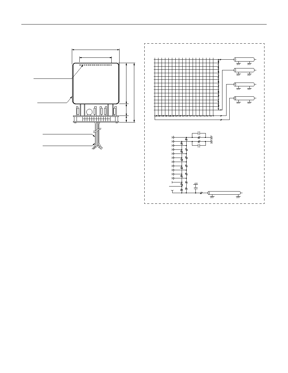
POSITION-SENSITIVE PHOTOMULTIPLIER TUBES R2487 SERIES
6
SIGNAL OUTPUT
: 0.8D COAXIAL CABLES
-H.V
: RG-174/U
PHOTOCATHODE
HA COATING
11.2
20
±
1
70
±
2
101.2
±
3
55(X)
◊
55(Y) MIN.
78
±
1
◊
78
±
1
Figure 9: R2487-02
TPMHC0087EC
TPMHA0161EF
Y
16
Y
15
Y
14
Y
13
Y
12
Y
11
Y
10
Y
9
Y
8
Y
7
Y
6
Y
5
Y
4
Y
3
Y
2
Y
1
X
5
X
6
X
7
X
8
X
9
X
10
X
11
X
12
X
13
X
14
X
15
X
16
X
4
X
3
X
2
X
1
X
17
X
18
EACH RESISTOR : 1k
Y
D
Y
C
X
B
X
A
RG174/U
DY
2
DY
1
DY
3
DY
4
DY
5
DY
6
DY
7
DY
8
DY
9
DY
10
DY
11
DY
12
K
Focus
10k
2R
2R
2R
2R
2R
1R
1R
1R
2R 1R
2R
C2
C3
C1
1R : 180k
1/2W
2R : 360k
1/2W
C
1
: 0.002
µ
F/2kV
C
2
: 0.01
µ
F/500V
C
3
: 0.01
µ
F/500V
HV
IN
2R
2R
2R
2R
2R
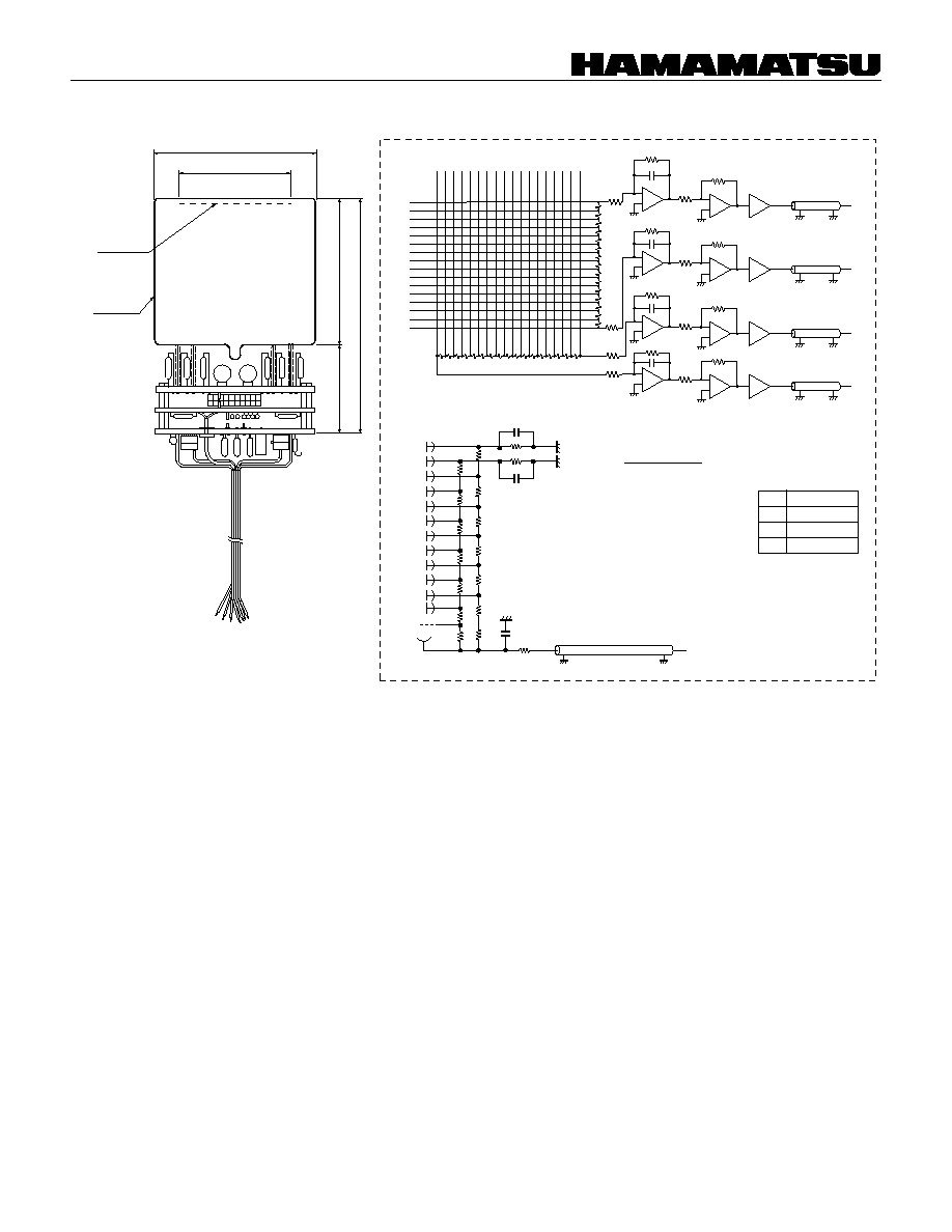
7
78
±
1
◊
78
±
1
55(X)
◊
55(Y) MIN.
PHOTO-
CATHODE
111
±
3
70
±
1
41
±
1
HA
COATING
Figure 10: R2487-05
TPMHC174EA
TPMHA0429EA
Y
16
Y
15
Y
14
Y
13
Y
12
Y
11
Y
10
Y
9
Y
8
Y
7
Y
6
Y
5
Y
4
Y
3
Y
2
Y
1
X
16
X
15
X
18
X
17
X
14
X
13
X
12
X
11
X
10
X
9
X
8
X
7
X
6
X
5
X
4
X
3
X
2
X
1
FOCUS
K
DY
12
DY
11
DY
10
DY
9
DY
8
DY
7
DY
6
DY
5
DY
4
DY
3
DY
2
DY
1
2R
2R
2R
2R
2R
2R
2R
2R
2R
1R
1R
1R
1R
1R : 180k
1/2W
2R : 360k
1/2W
C
1
: 0.002
µ
F/2kV
C
2
: 0.01
µ
F/500V
C
3
: 0.01
µ
F/500V
C
3
2R
2R
2R
C
1
C
2
-HV
10k
RG174
R
f
Y
D
Y
C
X
B
X
A
PRE-AMP SPEC.
Output signal :
57
Co + Nal(TI) : 0.2 to 1V
137
Cs + BGO : 0.1 to 0.5V
(Reference to next page)
Time Constant: 2
µ
s
Drive Ability: 50
Charge Sensitivity
(The included part can be
used instead of the socket.)
Rf
Sensitivity
10k
5V/pc
5k
2.5V/pc
1k
0.5V/pc
POSITION-SENSITIVE PHOTOMULTIPLIER TUBES R2487 SERIES
8
Nal (TI)
XA
R2487-05
57
Co
HAMAMATSU PHOTONICS K.K., Electoron Tube Center
314-5, Shimokanzo, Toyooka-village, Iwata-gun, Shizuoka-ken, 438-0193, Japan, Telephone: (81)539/62-5248, Fax: (81)539/62-2205
U.S.A.: Hamamatsu Corporation: 360 Foothill Road, P. O. Box 6910, Bridgewater. N.J. 08807-0910, U.S.A., Telephone: (1)908-231-0960, Fax: (1)908-231-1218
Germany: Hamamatsu Photonics Deutschland GmbH: Arzbergerstr. 10, D-82211 Herrsching am Ammersee, Germany, Telephone: (49)8152-375-0, Fax: (49)8152-2658
France: Hamamatsu Photonics France S.A.R.L.: 8, Rue du Saule Trapu, Parc du Moulin de Massy, 91882 Massy Cedex, France, Telephone: (33)1 69 53 71 00, Fax: (33)1 69 53 71 10
United Kingdom: Hamamatsu Photonics UK Limted: Lough Point, 2 Gladbeck Way, Windmill Hill, Enfield, Middlesex EN2 7JA, United Kingdom, Telephone: (44)181-367-3560, Fax: (44)181-367-6384
North Europe: Hamamatsu Photonics Norden AB: F‰arˆagatan 7, S-164-40 Kista Sweden, Telephone: (46)8-703-29-50, Fax: (46)8-750-58-95
Italy: Hamamatsu Photonics Italia: S.R.L.: Strada della Moia, 1/E, 20020 Arese, (Milano), Italy, Telephone: (39)02-935 81 733, Fax: (39)02-935 81 741
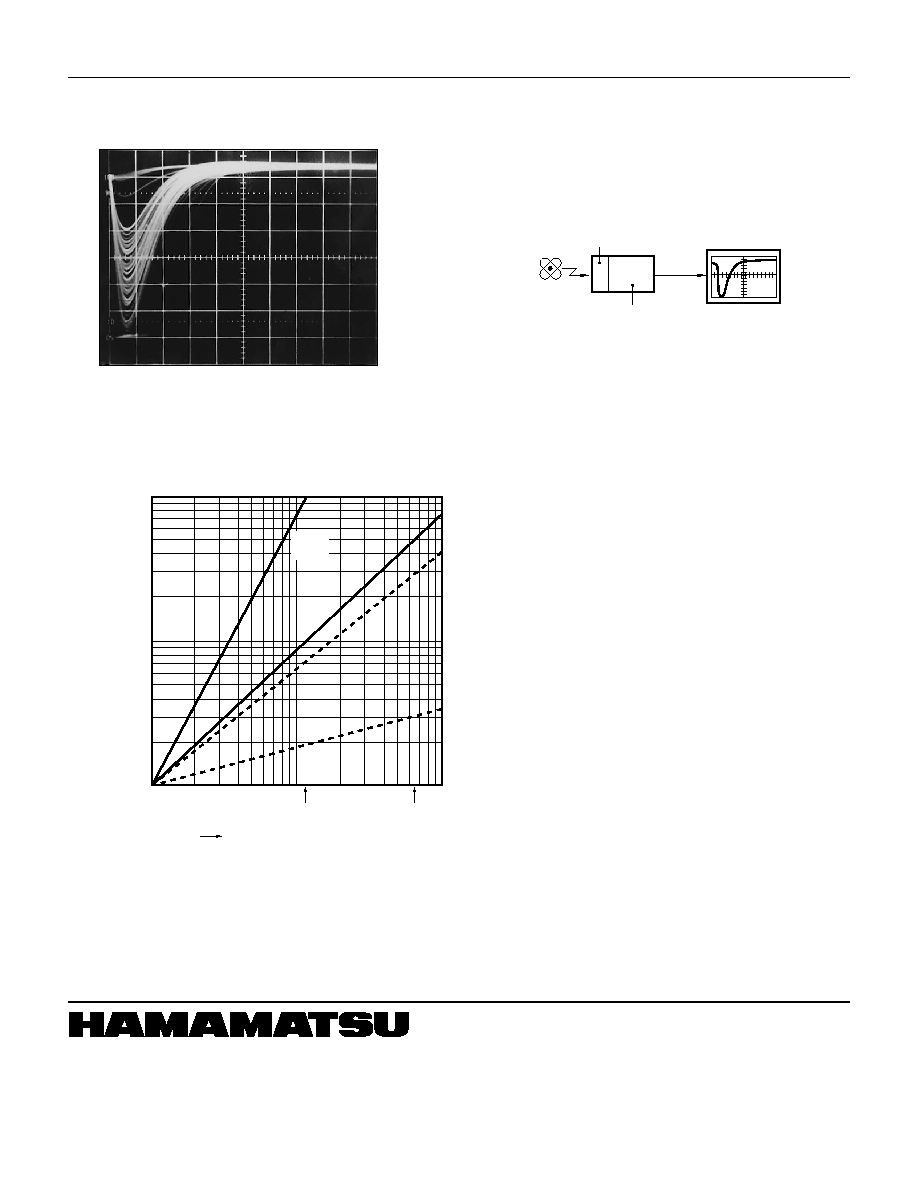
OUTPUT SIGNAL EXAMPLE OF R2487-05
2
µ
s, 0.2V/DIV.
TPMHF0063
CONDITION:
PMT Gain .......................................................... 1
◊
10
5
Scintillator ............................... Nal (TI) thickness 5 mm
Pre-Amp Sensitivity ......................................... 0.5 V/pc
10
100
0.5V/pc
BGO
5V/pc
BGO
0.5V/pc
Nal(TI)
500
1000
57
Co(121keV)
137
Cs(662keV)
0.1
5
1
0.5
INPUT ENERGY (keV)
OUTPUT SIGNAL OF PRE-AMP (V)
(PEAK VALUE)
OUTPUT SIGNAL VS. INPUT ENERGY
PARAMETER: PRE-AMP SENSITIVITY
: SCINTILLATOR
10
5V/pc
Nal(TI)
TPMHB0483EA
TPMH1207E01
JUL. 1998 IP
Printed in Japan