 | –≠–ª–µ–∫—Ç—Ä–æ–Ω–Ω—ã–π –∫–æ–º–ø–æ–Ω–µ–Ω—Ç: R3809u-50 | –°–∫–∞—á–∞—Ç—å:  PDF PDF  ZIP ZIP |
Information furnished by HAMAMATSU is believed to be reliable. However, no responsibility is assumed for possible inaccuracies or omissions. Specifications are
subject to change without notice. No patent rights are granted to any of the circuits described herein. ©2002 Hamamatsu Photonics K.K.
Subject to local technical requirements and regulations, availability of products included in this promotional material may vary. Please consult with our sales office.
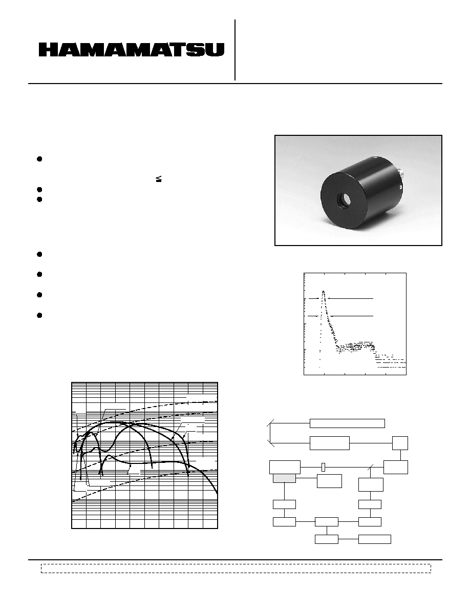
Compact MCP-PMT Series Featuring
Variety of Spectral Response with Fast Time Response
MICROCHANNEL PLATE-
PHOTOMULTIPLIER TUBE
(MCP-PMTs)
R3809U-50 SERIES
FEATURES
High Speed
Rise Time: 150 ps
T.T.S. (Transit Time Spread)
1)
: 25 ps(FWHM)
Molecular Science
Analysis of Molecular Structure
Medical Science
Optical Computer Tomography
Biochemistry
Fast Gene Sequencing
Material Engineering
Semiconductor Analysis
Crystal Research
Low Noise
Compact Profile
Useful Photocathode: 11 mm diameter
(Overall length: 70.2 mm Outer diameter: 45.0 mm)
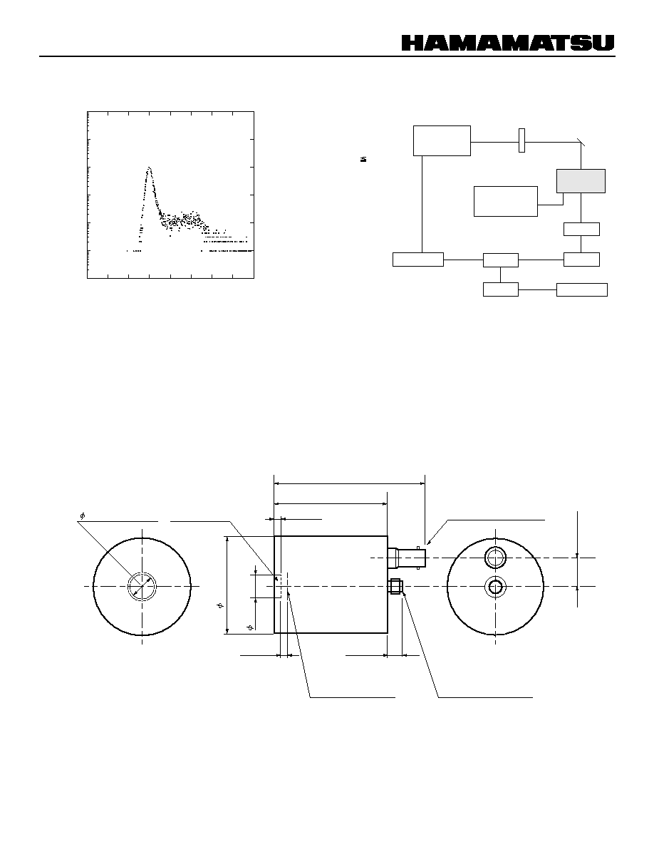
Figure 3: Block Diagram of T.T.S. Mesuring System
Figure 1: Spectral Response Characteristics
Figure 2: Transit Time Spread
APPLICATIONS
TPMHB0177EC
TPMHB0178EB
TPMHF0034
TPMHC0078EC
10
2
10
4
10
1
10
3
0
200
TIME (ps)
600
800
-200
COUNTS
400
PMT
SUPPLY VOLTAGE
LASER PULSE
WAVELENGTH
: R3809U-50
: -3000 V
: 5 ps (FWHM)
: 596 nm
FWHM 25.0 ps
FWTM 65.0 ps
100 200
400
600
800
300
500
700
900 1000 1100
10-
2
10-
1
10
0
10
1
10
2
10
3
WAVELENGTH (nm)
PHOTOCATHODE RADIANT SENSITIVITY (mA/W)
QE = 25%
-58
-53, -57
-50, -58
QE = 10%
-51
-59
QE =
0.1%
QE = 1%
-57
-50, 53
MODE LOCKED Nd-YAG LASER
PULSE
COMPRESSOR
DYE
JET
CAVITY
DUMPER
TRIGGER
CIRCUIT
DELAY
C.F.D.
COMPUTER
M.C.A.
T.A.C.
C.F.D.
AMP.
POWER
SUPPLY
MONOCHRO-
METER
LASER PULSE WIDTH: 5ps (FWHM)
FILTER
BS
MIRROR
MIRROR
START
STOP
TENNELEC
TC454 (=Oxford 454)
HAMAMATSU
PD S5973
HAMAMATSU
C3360
HAMAMATSU
C5594
ORTEC 457
R3809U-50

MCP-PMT R3809U-50 SERIES
MAXIMUM RATINGS (Absolute Maximum Values)
Parameter
Value
Supply Voltage
≠3400
100
≠50 to +50
Vdc
nA
Average Anode Current
350
mA
∞C
Pulsed Peak Current
10)
Unit
Ambient Temperature
11)
ELECTRICAL CHARACTERISTlCS (R3809U-50 ) at 25
∞C
3)
NOTES
Parameter
Min.
Typ.
Max.
Cathode Sensitivity
75
1)
2)
3)
4)
5)
6)
7)
8)
9)
10)
11)
Transit-time spread (TTS) is the fluctuation in transit time between individual pulse and specified as an FWHM (full width at half maximum) with the incident light
having a single photoelectron state.
Two microchannel plates (MCP) are incorporated as a standard but we can provide it with either one or three MCPs as an option depending upon your request.
This data is based on R3809U-50. All other types (suffix number 51 through 59) have different characteristics on cathode sensitivity and anode dark counts.
The light source used to measure the luminous sensitivity is a tungsten filament lamp operated at a distribution temperature of 2856K. The incident light intensity is
10
≠4
lumen and 100 volts is applied between the photocathode and all other electrodes connected as an anode.
This is the mean time difference between the 10 and 90% amplitude points on the output waveform for full cathode illumination.
This is the mean time difference between the 90 and 10% amplitude points on the tailing edge of the output waveform for full cathode illumination.
I.R.F. stands for Instrument Response Function which is a convolution of the
pulse function (H(t)) of the measuring system and the excitation function (E(t)) of a
laser. The I.R.F. is given by the following formula:
I.R.F. = H(t)
◊ E(t)
We specify the I.R.F. as an FWHM of the time distribution taken by using the measuring system in Figure 13 that is Hamamatsu standard I.R.F. measurement. It can
be temporary estimated by the following equation:
(I.R.F. (FWHM))
2
= (T.T.S.)
2
+ (Tw)
2
+ (Tj)
2
where Tw is the pulse width of the laser used and Tj is the time jitter of all equipments used. An I.R.F. data is provided with the tube purchased as a standard.
T.T.S. stands for Transit Time Spread (see
1)
above). Assuming that a laser pulse width (Tw) and time jitter of all equipments (Tj) used in Figure 3 are negligible,
I.R.F. can be estimated as equal to T.T.S.(see
8)
) above. Therefore, T.T.S. can be estimated to be 25 picoseconds or less.
This is specified under the operating conditions that the repetition rate of light input is 100 hertz or below and its pulse width is 70 picoseconds.
This is specified under either operation or storage except for R3809U-59. The ambient temperature for R3809U-59 under operation is specified -50
∞C to 0 ∞C.
We recommend use R3809U-51 and -59 with thermoelectric cooling unit to reduce dark counts (Refer to Figure 5)
Radiant at 430nm
150
50
Time Response
100
Gain at ≠3000 V
Unit
Luminous
4)
2
◊ 10
5
1
◊ 10
5
mA/W
Rise Time
5)
150
ps
Fall Time
6)
360
ps
I.R.F. (FWHM)
7)
45
8)
ps
T.T.S. (FWHM)
25
9)
ps
µA/lm
Anode Dark Counts at ≠3000 V
2000
s
-1
Voltage Divider Current at ≠3000 V
µA
GENERAL CHARACTERISTICS
SPECIFICATIONS
Parameter
Description/Value
Unit
Capacitance between Anode and MCP out
pF
3
Photocathode Useful Area in Diameter
mm
11
MCP Channel Diameter
µm
6
Weight
g
98
Dynode Structure
2)
2 - Stage Filmed MCP
PHOTOCATHODE SELECTION GUIDE
Suffix Number
Range
Peek Wavelength
Photocathode Material
Window Material
50
Synthetic Silica
Multialkali(S-20)
430
160 to 850
51
Synthetic Silica
Extended Multi. (S-25)
600
160 to 910
52
Synthetic Silica
Bialkali
400
160 to 650
53
Synthetic Silica
Cs-Te
230
160 to 320
57
MgF
2
Cs-Te
230
115 to 320
58
MgF
2
Multialkali (S-20)
430
115 to 850
59
Borosilicate
Ag-O-Cs (S-1)
800
400 to 1200
Spectral Response(nm)

TPMHB0179EA
TPMHB0182EA
TPMHB0181EA
TPMHB0180EC
TECHNICAL REFERENCE DATA
Figure 4: Typical DC Gain
Figure 5: Variation of Dark Counts Depending
on Ambient Temperature
-2.0
-2.2
-2.4
-2.6
-2.8
-3.0
-3.2
-3.4
10
2
10
3
SUPPLY VOLTAGE (kV)
10
4
10
5
10
6
10
7
CURRENT GAIN
Figure 7: Typical Output Deviation as a Function
of Anode Count Rate
Figure 6: Typical Output Deviation as a Function
of Anode DC Current
10
1
10
2
10
3
10
4
-100
-50
50
ANODE CURRENT (nA)
DEVIATION (%)
OVERALL SUPPLY VOLTAGE
MCP RESISTANCE
MCP STRIP CURRENT
: -3000 V
: 200 M
: 8.15
µA
10
5
10
6
10
7
10
8
-100
-50
50
COUNT RETE (cps.)
DEVIATION (%)
: -3000 V
: 200 M
: 8.15
µA
SUPPLY VOLTAGE
MCP RESISTANCE
MCP STRIP CURRENT
-40
-20
20
40
AMBIENT TEMPERATURE (
∞C)
DARK COUNT
(s
-
1
)
S-1
S-25
S-20
0
R3809U-50 SERIES
10-
1
10
0
10
1
10
2
10
3
10
4
10
5

MCP-PMT R3809U-50 SERIES
TPMHB0183EA
TPMHC0080EB
TPMHB0080EB
TPMHC0079EC
Figure 8: Typical Output Waveform
Figure 9: Block Diagram of Output Waveform Measuring
System
Figure 11: Block Diagram of PHD Measuring System
Figure 10: Typical Pulse Height Distribution (PHD)
TIME (0.2ns/div)
OUTPUT VOLTAGE (20mV/div)
SUPPLY VOLTAGE
RISE TIME
FALL TIME
PULSE WIDTH
: -3000 V
: 150 ps
: 360 ps
: 300 ps
PICOSECOND
LIGHT
PULSER
HAMAMATSU
MODEL#PLP-01
WAVELENGTH: 410 nm
PULSE WIDTH: 35 ps
ND FILTER
HAMAMATSU
C3360
Digital
Sampling
Osciloscope
PLOTTER
H.V.
Power
Supply
COMPUTER
R3809U-50
TEKTRONIX
11802
HALOGEN
LAMP
ND FILTER
HAMAMATSU
C3360
HIGH VOLTAGE
POWER
SUPPLY
CANBERRA 2005
COMPUTER
R3809U-50
PRE-
AMP.
LINEAR
AMP.
A-D
CONVERTER
M.C.A.
NAIG E-511A
Discriminater: 50 ch.
NEC PC9801
NAIG E-563A/E-562
NAIG E-522
200
50
400
600
800
1000
0
2
4
6
8
10
PULSE HEIGHT (CHANNEL NUMBER)
COUNTS (1
◊
10)
SUPPLY VOLTAGE
WAVELENGTH
AMBIENT TEMPERATURE
DARK COUNTS
PMT
PEAK
DISCRI.LEVEL
: -3000 V
: 410 nm
: 25
∞C
: 2000 s
-1
. (Max.)
: R3809U-50
: 200 ch.
: 50 ch.
SIGNAL + DARK COUNTS
DARK COUNTS
TPMHB0083EB
TPMHA0352EB
TPMHC0081EB
Figure 12: Typical Instrument Response Function (IRF)
Figure 13: Block Diagram of IRF Measuring System
Figure 14: Dimensional Outline (Unit: mm)
10
0
10
1
10
2
10
3
10
4
TIME (0.2ns/Div.)
FWHM: 45 ps
COUNTS (cps.)
PICOSECOND
LIGHT
PULSER
HAMAMATSU
MODEL#PLP-01
WAVELENGTH: 410 nm
FWHM: 35 ps
ND FILTER
HAMAMATSU
C3360
HIGH VOLTAGE
POWER
SUPPLY
COMPUTER
NEC PC9801
NAIG
DELAY
HAMAMATSU
C5594
TENNELEC TC-454
ORTEC 425A
ORTEC 457
LIGHT OUT
TRIGGER
SIGNAL
OUT
R3809U-50
MIRROR
M.C.A.
C.F.D.
AMP.
T.A.C.
START
STOP
3.2±0.1
7.0±0.2
13.7±0.1
52.5±0.1
70.2±0.3
3.0±0.2
45.0±0.1
11MIN.
≠H.V INPUT
SHV-R CONNECTOR
ANODE OUTPUT
SMA-R CONNECTOR
WINDOW
FACE PLATE
PHOTOCATHODE
EFFECTIVE
PHOTOCATHODE
DIAMETER
11.0 MIN.

MCP-PMT R3809U-50 SERIES
PRECAUTIONS FOR PROPER OPERATION
Handling on set-up
1)
2)
3)
4)
5)
The photomultiplier tube (PMT) is a glass product under high vacuum. EXCESSIVE PRESSURE, VIBRATIONS OR
SHOCKS TO THE TUBE FROM THE SURROUNDING COULD CAUSE A PERMANENT DAMAGE. Please pay special
attention on insuring proper handling.
DO NOT PLACE ANY OBJECTS OF GROUND POTENTIAL CLOSER THAN 5mm TO THE PHOTOCATHODE WINDOW
when negative high voltage is applied to the photocathode. It could generate extra noise and damage the photocathode
permanently.
DO NOT EXPOSE THE PHOTOCATHODE TO SUNLIGHT DIRECTLY and any light stronger than the room light even
during of no operation.
NEVER TOUCH THE INPUT WINDOW WITH YOUR BARE HANDS. In case the window contaminated by dust or grease,
wipe it off using alcohol and a soft cloth or dust free tissue.
DO NOT OPERATE OR STORE IN A PLACE OF UNSPECIFIED TEMPERATURE AND HUMIDITY.
Supplying high voltage
1)
2)
3)
4)
DO NOT SUPPLY ANY VOLTAGE HIGHER THAN SPECIFIED. Also make sure the output current does NOT EXCEED
THE MAXIMUM CURRENT specified.
This device is very sensitive even with weak light input. When applying high voltage to the tube, GRADUALLY (IDEALLY
100 Vdc STEP BUT 500 Vdc STEP IS OK) AND CAREFULLY INCREASE THE VOLTAGE while monitoring the output using
an ammeter or oscilloscope. Also make sure before use that the polarity of the applied voltage is correct.
DO NOT REMOVE OR CONNECT ANY INPUT OR OUTPUT CABLES WHILE HIGH VOLTAGE IS APPLIED. If a high
voltage is applied when its output is opened, DO NOT CONNECT ANY READOUT CIRCUIT TO THE TUBE IMMEDIATELY
after turning the high voltage off. Ground the anode of the tube before connecting in order to avoid possible damage to the
readout circuit due to an excessive electron charge flowing from its anode.
IT IS RECOMMENDED TO TURN HIGH VOLTAGE OFF WHILE NOT BEING USED FOR MEASUREMENTS. This is to
avoid shortening its period of life time as well as a risk of damage due to an exposure of excessive incident light.
Incident light amount
1)
2)
3)
KEEP THE INCIDENT LIGHT AMOUNT AS LOWS AS POSSIBLE to extend its period of life time.
In a case of photon counting application, it is recommended to KEEP THE SIGNAL COUNT RATE LESS THAN 20kcps.
ILLUMINATE PHOTOCATHODE EFFECTIVE AREA AS LARGE AS POSSIBLE to keep better linearity characteristics and
avoid an excessive stress in partial area, which may result in a reduction of sensitivity partially.
Usage in vacuum
1)
2)
3)
4)
DO NOT USE A PMT AS AN INTERFACE BETWEEN VACUUM AND ENVIRONMENTAL PRESSURE.
Standard MCP-PMT is not designed for vacuum-tight construction.
KEEP THE TUBE CLEAN. Unless otherwise, it would cause outgassing in a vacuum.
DO NOT SUPPLY HIGH VOLTAGE UNLESS THE VACUUM LEVEL REACHES 1
◊ 10
≠3
Pa OR HIGHER.
DO NOT PROCEED BAKING VACUUM INSTRUMENTS WHILE THE TUBE IS PLACED INSIDE.
OTHERS
1) If the tube won't be used with a cooler, it is recommended to LEAVE THE TUBE IN DARKNESS (YOUR INSTRUMENT
WITHOUT ANY INPUT LIGHT) FOR 30 MINUTES OR SO before start any measurements because it occasionally takes a
little while until its dark noise settles down.
WARRANTY
The detectors indicated in this data sheet are warranted to the original purchaser for a period of 12 MONTHS following the date
of shipment. The warranty is limited to repair or replacement of any defective material due to defects in workmanship or
materials used in manufacture.
1)
2)
3)
4)
5)
Any claim for damage of shipment must be made directly to the delivering carrier within five days.
Customer must inspect and test all detectors within 30 days after shipment. Failure to accomplish said incoming inspection
shall limit all claims to 75% of invoice value.
No credit will be issued for broken detector unless in the opinion of Hamamatsu the damage is due to a manufacturing defect.
No credit will be issued for any detector which in the judgement of Hamamatsu has been damaged, abused, modified or
whose serial number or type number have been obliterated or defaced.
No detector will be accepted for return unless permission has been obtaind from Hamamatsu in writing, the shipment has
been returned repaired and insured, the detector is packed in their original box and accompanied by the original data sheet
furnished to the customer with the tube, and a full written explanation of the reason for rejection of detector.
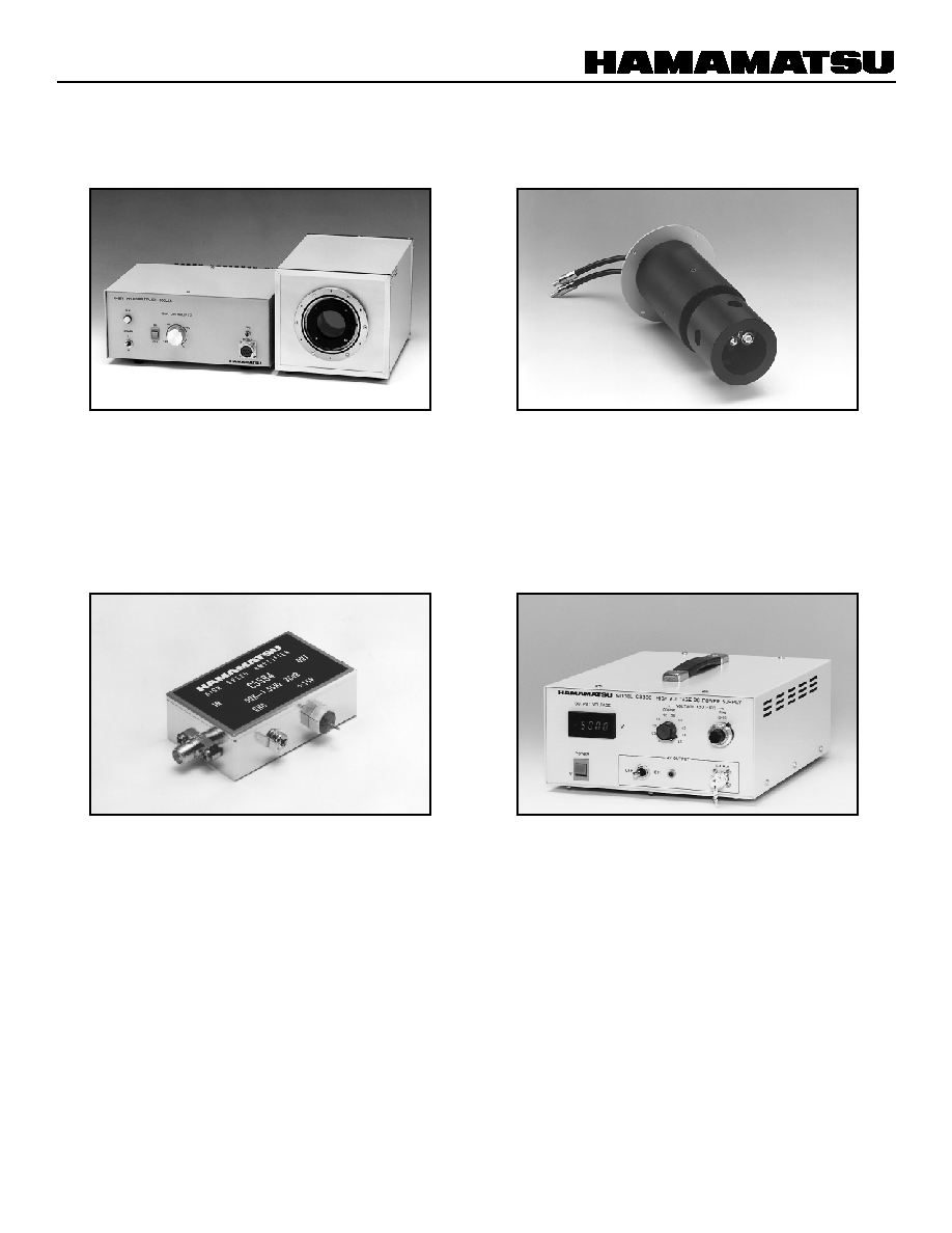
ACCESSORIES
THERMOELECTRIC COOLING UNIT
C4878
Specifications
Note: C4878 reguires a holder (e.g E3059-500 for R3809U-50 series).
Cooling ..................................................................................
Heat exchange Medium (coolant) .............................
Temperature controllable range .........................................................
Optical window material .....................................
Thermoelectric Effects
Water (1/3 litters/min. flow rate)
≠30
∞C to 0 ∞C
Evacuated double-pane fused silica
Specifications
Frequency Response Range .............
Gain ............................................................
Input/Output Impedance .........................................
Noise Figure (NF) ..........................................
Supply Voltage .........................................
Recommend Input Voltage ...................................
Supply Current ...........................................
50 kHz to 1.5 GHz
36 dB(Typ.)
50
7 dB(Typ.)
+12 to +16 V
+15 V
95 mA(Typ.)
Output Voltage ...........................................
Maximum Output Current ......................................
0 to ≠5000 V
1 mA
Absolute Maximum Ratings
Supply Voltage .....................................................
Input Power ........................................................
+17 V
10 mW
Output Stabilities
Input Regulation .................
(For ± 10 % change in input voltage)
Load Regulation .................
(For 0 to 100 % change in load)
Ripple ...............................................
Drift ..................................................
(After 1h warm-up)
±(0.001 % + 0.05 V)Max.
±(0.001 % + 0.05 V)Max.
20 mV p-p Max.
±0.02 %/h Max.
HOLDER
E3059-500
HIGH SPEED AMPLIFIER
C5594 Series
HIGH VOLTAGE POWER SUPPLY
C3360

TPMH1067E07
FEB. 2002 IP
MCP-PMT R3809U-50 SERIES
HAMAMATSU PHOTONICS K.K., Electron Tube Center
314-5, Shimokanzo, Toyooka-village, Iwata-gun, Shizuoka-ken, 438-0193, Japan, Telephone: (81)539/62-5248, Fax: (81)539/62-2205
U.S.A.: Hamamatsu Corporation: 360 Foothill Road, P. O. Box 6910, Bridgewater. N.J. 08807-0910, U.S.A., Telephone: (1)908-231-0960, Fax: (1)908-231-1218 E-mail: usa@hamamatsu.com
Germany: Hamamatsu Photonics Deutschland GmbH: Arzbergerstr. 10, D-82211 Herrsching am Ammersee, Germany, Telephone: (49)8152-375-0, Fax: (49)8152-2658 E-mail: info@hamamatsu.de
France: Hamamatsu Photonics France S.A.R.L.: 8, Rue du Saule Trapu, Parc du Moulin de Massy, 91882 Massy Cedex, France, Telephone: (33)1 69 53 71 00, Fax: (33)1 69 53 71 10 E-mail: infos@hamamatsu.fr
United Kingdom: Hamamatsu Photonics UK Limited: 2 Howard Court, 10 Tewin Road Welwyn Garden City Hertfordshire AL7 1BW, United Kingdom, Telephone: 44-(0)1707-294888, Fax: 44(0)1707-325777 E-mail: info@hamamatsu.co.uk
North Europe: Hamamatsu Photonics Norden AB: Smidesv‰gen 12, SE-171-41 SOLNA, Sweden, Telephone: (46)8-509-031-00, Fax: (46)8-509-031-01 E-mail: info@hamamatsu.se
Italy: Hamamatsu Photonics Italia: S.R.L.: Strada della Moia, 1/E, 20020 Arese, (Milano), Italy, Telephone: (39)02-935 81 733, Fax: (39)02-935 81 741 E-mail: info@hamamatsu.it
HOMEPAGE URL http://www.hamamatsu.com