 | –≠–ª–µ–∫—Ç—Ä–æ–Ω–Ω—ã–π –∫–æ–º–ø–æ–Ω–µ–Ω—Ç: R7400U | –°–∫–∞—á–∞—Ç—å:  PDF PDF  ZIP ZIP |

R7400U SERIES
METAL PACKAGE
PHOTOMULTIPLIER TUBE
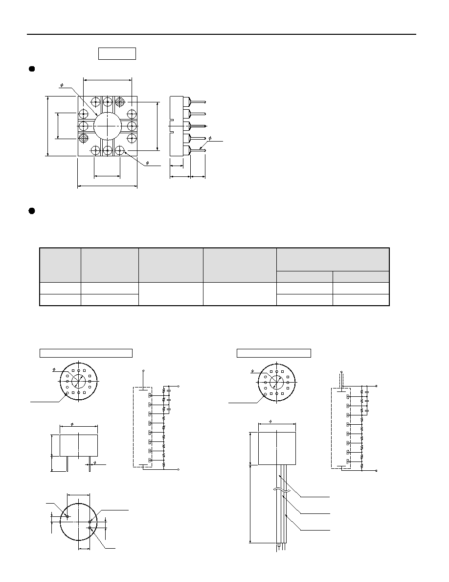
VOLTAGE DISTRIBUTION RATIO
Left: R7400U Right: R7401/R7402
Electrodes
K
1
Dy1
1
Dy2
1
Dy3
1
Dy4
1
Dy5
1
1
Dy6
Dy7
1
Dy8
0.5
P
Ratio
SERIES
GENERAL
Solar Blind
UV to Visible Range
R7400U/R7400U-03/R7400U-06
R7400P
R7401 (Visible Range)
R7400U-01/R7400U-02/R7400U-04/R7400U-20
Yes
Unit
UV to Near IR Range
--
Yes
R7402 (Visible to Near IR Range )
Yes
Insulation Cover
R7400U-09
--
--
Standard
Parameter
Minimum Effective Area
Dynode
Description/Value
8
Metal Channel
8
Structure
Number of Stage
R7400U Series/R7400P
Weight
R7401/R7402/R7401P
Ambient Temperature
R7400U Series/R7400P
R7401/R7402/R7401P
Approx. 5.3
Approx. 6.3
-80 to +50
-30 to +50
For Photon Counting
With Lens
Supply Voltage: 800 V K: Cathode Dy: Dynode P: Anode
The R7400U series is a subminiature photomultiplier tube with a
16 mm diameter and 12 mm seated length. A precision engi-
neered 8-stage electron multiplier (composed of metal channel
dynodes) is incorporated in the TO-8 package to produce a noise
free gain of 700,000 times (R7400U). The R7400U series also
features excellent response time with a rise time of 0.78 ns. Vari-
ous types of the R7400U series are available with different spec-
tral response and gain ranges, including those selected specifi-
cally for photon counting applications. Hamamatsu also provides
a hemispherical lens input option to the series (R7401 and
R7402), effectively doubling the active area.
FEATURES
World's smallest photomultiplier tubes assembled in a TO-8 metal package (1/7th of the Hamamatsu R647).
The necessary components are built into a TO-8 package while retaining full photomultiplier tube performance to cre-
ate a new generation of photosensors.
Photon counting type: R7400P.
The R7400P is specially selected on account of low noise and high gain for use in photon counting applications.
Hemispherical lens window types: R7401 (bialkali), R7402 (multialkali).
The hemispherical lens window doubles the effective input area to 12 mm in diameter.
Compact size (16 mm diameter, 12 mm seated length),
Fast Time response (rise time 0.78 ns)
mm
--
g
∞C
Information furnished by HAMAMATSU is believed to be reliable. However, no responsibility is assumed for possible inaccuracies or omissions. Specifications are
subject to change without notice. No patent rights are granted to any of the circuits described herein. ©2001 Hamamatsu Photonics K.K.
Subject to local technical requirements and regulations, availability of products included in this promotional material may vary. Please consult with our sales office.

Spectral Response
Maximum Ratings
Peak
Wave-
Iength
(nm)
Range
(nm)
Anode to
Cathode
Voltage
Radiant
Typ.
(mA/W)
◊10
-3
Blue(5-58)
Typ.
(
µA/lm-b)
Out-
line
No.
Typ.
(
µA/lm)
Min.
(
µA/lm)
Cathode Sensitivity
Luminous
R7400U-09
Solar Blind
UV to Visible
Visible
Visible
UV to Near IR
With Lens
R7400U
R7400U-03
R7400U-06
R7400U-01
R7400U-02
R7400U-20
R7400U-04
R7401
(a): Measured at 254 nm.
(b): Measured after a 30-minute storage in darkness.
R7402
160 to 320
300 to 650
185 to 650
160 to 650
300 to 850
300 to 880
185 to 850
300 to 650
300 to 850
240
420
400
500
300 to 900
630
400
400
420
Cs-Te
Bialkali
Multialkali
Bialkali
Multialkali
Synthetic silica
Synthetic silica
Window
Material
Remarks
Type No.
Photo-
cathode
Material
Borosilicate glass
Borosilicate glass
Borosilicate glass
UV glass
UV glass
1000(d)
0.01
0.1(e)
--
40
80
200
80
40
80
--
70
150
250
350
500
150
70
150
--
8
--
--
8
--
--
--
200
250
200
200
22(a)
62
60
58
450
78
(at 630 nm)
60
62
60
TPMHB0473EA
TPMHB0474EA
TPMHB0475EB
TPMHB0491EB
Figure 1: Typical Spectral Response (Solar Blind)
Figure 2: Typical Spectral Response (Bialkali)
Figure 3: Typical Spectral Response (Multialkali)
Figure 4: Typical Gain Characteristics
METAL PACKAGE PHOTOMULTIPLIER TUBE R7400U SERIES
CHARACTERISTICS (at 25
∞C)
(mA)
(V dc)
Average
Anode
Current
Red/White
Ratio
Typ.
(c): Measured at a gain of 10
6
(d): Do not apply the maximum supply voltage for more than 30 seconds continuously.
100
300
200
400
500
600
WAVELENGTH (nm)
0.1
1
10
PHOTOCATHODE RADIANT SENSITIVITY (mA / W)
100
0.01
R7400U-09
200
100
400
300
600
500
800
700
1
10
100
0.1
WAVELENGTH (nm)
PHOTOCATHODE RADIANT SENSITIVITY (mA / W)
R7400U
R7400U-03
R7400U-06
SUPPLY VOLTAGE (V)
GAIN
100
200
400
600
800 1000
10
1
10
6
10
4
10
5
10
3
10
2
10
7
R7400U-09
R7400U/-03/-06
R7400P
WAVELENGTH (nm)
CATHODE RADIANT SENSITIVITY (mA / W)
100
200
300
400 500
600
700
800
900 1000
0.1
1
10
100
R7400U-04
R7400U-02
R7400U-01
R7400U-20

Figure 5: Typical Gain Characteristics
Figure 7: Anode Dark Current (v.s. Temperature)
TPMHB0492EC
TPMHB0478EA
(V dc)
Dark Count (c)
(s
-1
)
Gain
Gain
For Photon Counting (P Type)
Type No.
Max.
R7400P
400
80
1
◊ 10
6
7.5
◊ 10
5
R7401P
Typ.
Typ.
Min.
Min.
(A/lm)
Typ.
(A/lm)
Typ.
(A/W)
Typ.
Max.
(nA)
Typ.
(nA)
RiseTime
Typ.
(ns)
Anode Characteristics
Luminous
Anode Sensitivity
R7400U-09
R7400U
R7400U-03
2
0.5
R7400U-06
R7400U-01
5.4
0.78
R7400U-02
R7400U-20
R7400U-04
R7401
2
4
20
4
4
0.2
0.025
0.2
0.4
2
0.4
0.4
7
◊ 10
5
5
◊ 10
4
7
◊ 10
5
5
◊ 10
5
5
◊ 10
5
4.3
◊ 10
4
1100(a)
4.3
◊ 10
4
3.0
◊ 10
4
2.9
◊ 10
4
3.9
◊ 10
4
3.0
◊ 10
4
3.0
◊ 10
4
50
--
50
125
75
10
--
10
25
250
35
75
15
75
15
15
800
R7402
Type No.
Time Response
Anode Dark
(b)
Current
Radiant
Figure 6: Anode Dark Current (v.s. Supply Voltage)
TPMHB0477EB
Anode to
Cathode
Supply
Voltage
Electron
Transit Time
Typ.
(ns)
(e): The output current averaged over 30 seconds should not exceed 0.1 mA.
SUPPLY VOLTAGE (V)
GAIN
100
200
400
600
800 1000
10
1
10
6
10
4
10
5
10
3
10
2
10
7
R7400U-01/-02/-04/-20
SUPPLY VOLTAGE (V)
Anode Dark Current (nA)
100
200
400
600
1000
800
0.001
0.01
0.1
1
10
R7400U-02/-20
R7400U-01/-04
R7400U/-03/-06
R7400U-09
0.01
100
0.01
0.1
1
10
R7400U/03/06
Supply Voltage: -800 V
R7400U-01/04
TEMPERATURE (
∞C)
ANODE DARK CURRENT (nA)
-10
10
30
50
-20
0
20
40

TPMSB0137EB
TPMHC0153EA
TPMHB0461EB
TPMHB0462EB
Figure 10: Lens Effect
Parallel light : Parallel Light: from a 40 mm diameter parallel light source insuring uniform
intensity over the entire active area of the photomultiplier tube.
Diffused light: Diffused light: from a 40 mm diameter parallel light source and a diffuser placed
10cm from the detector. The entire active area of the PMT is exposed.
Figure 8: Transmittance of Lens
Figure 9: Lens Effect
R7401
R7402
200
0
10
20
30
40
50
60
70
80
90
100
300
400
500
600
700
800
900
WAVELENGTH (nm)
TRANSMITTANCE (%)
0
50
100
0
50
100
MEASUREMENT CONDITIONS
WAVELENGTH : 400 nm
SUPPLY VOLTAGE : -800 V
WITHOUT LENS
WITH LENS
ANODE SENSITIVITY
LENS
A 1 mm diameter spot light (parallel light) is scanned
at the center of the photocathode in X and Y directions.
0
X-AXIS(mm)
7
7
0
Y-AXIS(mm)
7
7
WAVELENGTH (nm)
RELATIVE OUTPUT (
%
)
300
0
50
100
150
200
250
300
400
500
600
700
WITH LENS
∑
PARALLEL LIGHT
WITH LENS
∑
DIFFUSED LIGHT
WITHOUT LENS
PMT: R7400U
SUPPLY VOLTAGE: -800 V
WAVELENGTH (nm)
RELATIVE OUTPUT (
%
)
WITH LENS
∑
PARALLEL LIGHT
WITH LENS
∑
DIFFUSED LIGHT
300
0
50
100
150
200
250
300
400
500
600
700
800
850
900
WITHOUT LENS
PMT: R7400U-01
SUPPLY VOLTAGE: -800 V
METAL PACKAGE PHOTOMULTIPLIER TUBE R7400U SERIES

3R7401, R7402, R7401P
2R7400U-06,-09
1R7400U, -01, -02, -03, -04, -20, R7400P
Figure 11: Dimensional Outline and Basing Diagram (Unit: mm)
DY4
DY2
DY1
K
DY3
1
2
3
4
5
6
7
8
9
10
11
12
DY5
DY7
P
DY8
DY6
SHORT PIN
(IC)
SHORT PIN
(IC)
IC: Internal Connection
(Do not use)
TPMHA0411EC
TPMHA0410EC
TPMHA0415EC
10.16
5.08
10.16
5.08
12- 0.45
INSULATION COVER (Polyoxymethylene)
PHOTOCATHODE
8 MIN.
0.5
± 0.2
11.5
± 0.4
4.0
± 0.3
Bottom View
Side View
5
± 1
SHORT PIN
GUIDE MARK
5.4
±
0.3
15.9
±
0.4
WINDOW
9.4
±
0.4
10.16
5.08
10.16
5.08
12- 0.45
PHOTOCATHODE
8MIN.
11.5
± 0.4
19
± 0.5
4.0
± 0.3
Bottom View
Side View
5
± 1
SHORT PIN
GUIDE MARK
5.4
±
0.3
15.9
±
0.4
14
±
0.3
SR7
INSULATION COVER (Polyoxymethylene)
INSULATION COVER (Polyoxymethylene)
10.16
5.08
10.16
5.08
12- 0.45
PHOTOCATHODE
8MIN.
12.8
± 0.5
4.0
± 0.3
Bottom View
Side View
SHORT PIN
GUIDE MARK
5.4
±
0.3
WINDOW
11.0
±
0.4
15.9
±
0.4
0.3
± 0.2
5
± 1
ACCESSORIES OPTION
Cable Output Type E5780
Socket E678-12M
D Type Socket Assemblies E5770/E5780
Type No.
E5770
E5780
Pulse
--
DC/Pulse
Cathode Grounded Anode Grounded
DC/Pulse
Anode/Cathode
Anode
Grounded
Electrode
2.8 M
13
µA
Output Signal
Maximum Linear
Output of
Photomultiplier Tube
(DC Mode)
Divider Resistance
(Total)
PC-board Mounting Type E5770
TACCA0060EC
TACCA0057EF
TACCA0059EC
The E5770 and E5780 are compact socket assemblies incorporating a voltage divider circuit comprised of resistors
and capacitors. These socket assemblies are designed to provide the output signal directly from the anode of the
metal package photomultiplier tube.
* When the E5770 is used with the anode at a positive high voltage, the negative high voltage (-HV) terminal should be grounded
and a positive high voltage applied to the ground terminal. In this arrangement, a high voltage differential is generated between the
output and an external amplifier, so use a decoupling capacitor that can withstand a high voltage.
** In the E5780, the shield of the signal output cable is connected to the grounded cable, so the E5780 can be used only for negative
high voltage operation. Consult our sales office when the E5780 is needed for positive high voltage operation.
DY5 DY3
K
DY1
DY2
DY8
DY6
DY4
DY7
P
6.0
12.5
1.83
5.08
12.5
2.8
4.2
3.2
0.53
Top View
Side View
5.08
10.16
10.16
METAL PACKAGE PHOTOMULTIPLIER TUBE R7400U SERIES
17
±0.2
7
10
±
0.5
2.54
10.16
5.08
-HV
GND
SIGNAL OUT
0.45
GUIDE MARK
Top View
Side View
Bottom View
2.54
DY8
DY7
DY6
DY5
DY4
DY3
DY2
DY1
R9
R8
R7
R6
R5
R4
R3
R2
R1
C3
C2
C1
GND or +HV
P
K
-HV or GND
R1 to R8
R9
C1 to C3
: 330 k
: 160 k
: 0.01
µF/ 200 V
SIGNAL OUT
6
For +HV, it will be necessary to use a
coupling capacitor between the output
and the customer's signal processing
circuit.
DY8
DY7
DY6
DY5
DY4
DY3
DY2
DY1
R9
R8
R7
R6
R5
R4
R3
R2
R1
C3
C2
C1
GND: AWG22
(BLACK)
P
K
-HV: AWG22
(VIOLET)
R1 to R8
R9
C1 to C3
: 330 k
: 160 k
: 0.01
µF /200 V
SIGNAL OUT
RG-174/U
15
±
0.5
450
-HV: AWG22
(VIOLET)
GND: AWG22
(BLACK)
17
±0.2
SIGNAL OUT:
RG-174 /U
Side View
GUIDE MARK
Top View
6

Parameter
Value
Unit
Input Voltage for Amplifier
±15
V
Current to Voltage Conversion Factor
1
V/
µA
Maximum Output Voltage (with no load resistor)
10
V
Bandwidth (-3 db)
DC to 20
kHz Typ.
SPECIFICATION of Built-in Amplifier
Parameter
C4900
+15 V dc
0.6 mA
+12 V dc
0 V to -1250 V
0 V to +1250 V
0.5 mA
+15 V dc
0.6 mA
+12 V dc
14 mA
15 mA
14 mA
15 mA
90 mA
95 mA
90 mA
95 mA
0.5 mA
0.007 % p-p Typ.
±0.01 % p-p Typ.
±
0.01 % p-p Typ.
C4900-01
C4900-50
C4900-51
Input Voltage
Input Current
1
2
Variable Output Range
Maximum Output Current
Ripple Noise
Line Regulation *B
Load Regulation *C
SPECIFICATION
Compact High Voltage Power Supply Units
C4900 Series
The C4900 series is an on-board type high voltage power
supply unit, with a design that aims at providing both
"compactness and high performance".
The newly developed circuit achieves high performance
and low power consumption. The C4900 series in addition
provides enhanced protective functions yet is offered at
lower costs.
DA Type Socket Assembly C5781
1with no load
2with full load
*A: at maximum output voltage
*B: against
±1 V Change.
*C: against 0 to 100 % Load Change.
The C5781 is a subminiature socket assembly that
incorporates a voltage divider circuit and a low-noise
amplifier.
TACCA0061EC
25
GND: AWG22 (BLACK)
17.0
±0.2
+15 V: AWG22 (RED)
SIGNAL OUT: RG-174/U
-15 V: AWG22 (BLUE)
450
DY8
DY7
DY6
DY5
DY4
DY3
DY2
DY1
R9
R8
R7
R6
R5
R4
R3
R2
R1
C3
C2
C1
POWER SUPPLY
GND: AWG22 (BLACK)
K
-HV: AWG22 (VIOLET)
R1 to R8
R9
C1 to C3
: 330 K
: 160 K
: 0.01
µF/200 V
P
SIGNAL OUT
RG-174/U
SIGNAL GND
+15 V: AWG22 (RED)
-15 V: AWG22 (BLUE)
AMPLIFIER
GUIDE MARK
-HV: AWG22 (VIOLET)
6
*A

TPMH1204E06
AUG. 2001 IP
(1000)
WARNING: HIGH VOLTAGE
The H6779/H6780 series are new light sensor mod-
ules including the compact photomultiplier tube,
(METAL PACKAGE PMT) and operating power
supply. It features low voltage operation (+15 V)
and low power consumption (Approx. 450 mW for
H6779/H6780). Compared with current light sen-
sors, it has several advantages like high sensitivity,
wide dynamic range and fast time response. These
are featured by the PMT and the Cockcroft-Walton
high voltage power supply. The H5773/H6779 ser-
ies are on-board types which facilitates mounting
directly on a printed circuit board and the
H5783/H6780 series have a cable output. H5784
series are cable out type with an amplifier of DC to
20 kHz bandwidth. These versions accept direct
light input or an optical fiber with the optional fiber
connector of E5776.
FEATURES
Low Power Consumption
Low Voltage Drive
Easy to Use
High Sensitivity
Wide Dynamic Range
Fast Time Response
: SIZE 25(W)
◊ 50(D) ◊ 18(L) mm WEIGHT: 50 g
: SIZE 22(W)
◊ 22(D) ◊ 50(L) mm WEIGHT: 80 g
: SIZE 22(W)
◊ 22(D) ◊ 60(L) mm WEIGHT: 100 g
H5773, H6779 Series
H5783,H6780 Series
H5784 Series
PHOTOSENSOR MODULES H6779/H6780/H5784 SERIES
H6779 Series
The metal package photomultiplier tubes are operated by applying a high voltage. Use extreme caution
to avoid electrical shock and damage to the peripheral equipment and be sure to provide adequate safety
measures as needed. As safety measures, an insulation cover is fitted to the metal package which is
electrically connected to the photocathode. When operated with the cathode at a high voltage (anode
ground scheme), the metal package will be at this same high voltage level. Removing the insulation
cover is extremely dangerous, so never attempt to remove it from the package.
TPMHC0093EB
PATENT: USA 1 (PAT. No. 5410211) PATENT PENDING: JAPAN 12, USA 8, EUROPE 9
RELATED PRODUCTS
Left: H6780 Center: H6779 Right: H6779 with E5776
Front: METAL PACKAGE PMT
METAL PACKAGE PMT
HIGH VOLTAGE
POWER SUPPLY
Please refer the individual detail data sheet of
H6779/H6780/H5784 series
HIGH VOLTAGE
METAL PACKAGE PHOTOMULTIPLIER TUBE R7400U SERIES
HAMAMATSU PHOTONICS K.K., Electron Tube Center
314-5, Shimokanzo, Toyooka-village, Iwata-gun, Shizuoka-ken, 438-0193, Japan, Telephone: (81)539/62-5248, Fax: (81)539/62-2205
U.S.A.: Hamamatsu Corporation: 360 Foothill Road, P. O. Box 6910, Bridgewater. N.J. 08807-0910, U.S.A., Telephone: (1)908-231-0960, Fax: (1)908-231-1218 E-mail: usa@hamamatsu.com
Germany: Hamamatsu Photonics Deutschland GmbH: Arzbergerstr. 10, D-82211 Herrsching am Ammersee, Germany, Telephone: (49)8152-375-0, Fax: (49)8152-2658 E-mail: info@hamamatsu.de
France: Hamamatsu Photonics France S.A.R.L.: 8, Rue du Saule Trapu, Parc du Moulin de Massy, 91882 Massy Cedex, France, Telephone: (33)1 69 53 71 00, Fax: (33)1 69 53 71 10 E-mail: infos@hamamatsu.fr
United Kingdom: Hamamatsu Photonics UK Limited: 2 Howard Court, 10 Tewin Road Welwyn Garden City Hertfordshire AL7 1BW, United Kingdom, Telephone: 44-(0)1707-294888, Fax: 44(0)1707-325777 E-mail: info@hamamatsu.co.uk
North Europe: Hamamatsu Photonics Norden AB: Smidesv‰gen 12, SE-171-41 SOLNA, Sweden, Telephone: (46)8-509-031-00, Fax: (46)8-509-031-01 E-mail: info@hamamatsu.se
Italy: Hamamatsu Photonics Italia: S.R.L.: Strada della Moia, 1/E, 20020 Arese, (Milano), Italy, Telephone: (39)02-935 81 733, Fax: (39)02-935 81 741 E-mail: info@hamamatsu.it
HOMEPAGE URL http://www.hamamatsu.com