1
Memory Stick
ģ
Connectors
CB1 Series
NEW
NEW
2003.12
s
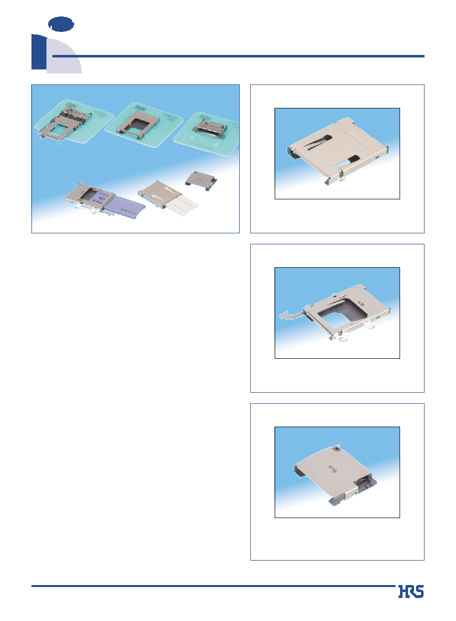
Outline
Receptacle connectors for use with the new generation of
digital media devices requiring "Memory Stick
ģ
" type of
consumer removable memory card.
Several variations are available: Miniature, Low Profile and
with or without ejection mechanism.
s
Features
1. Indication of Incorrect Card Insertion
The connector will not allow the card to be complete
inserted from the wrong end or reversed.
The card will stop about 7mm before complete insertion
position, visually indicating incorrect insertion.
2. Protection of the Contacts
Incorrect insertion of the card will not damage the
contacts. The card can be easily withdrawn and re-
inserted correctly.
3. Excellent Card Handling
The type that is equipped with an ejection mechanism
provides a long ejection of the card which offers excellent
card handling qualities.
*Memory Stick is a registered trademark of the Sony Corporation.
Card Push Insert/Push Eject
<CB1G Series>
q Card ejection distance of 10 mm
q Mounting height of 3.5 mm
q Mounting area: Smaller design is 78% of former
size
Button Touch Ejection
<CB1F Series>
q Card ejection with tactile button operation
q Card ejection distance of 10 mm
q Equipped with card ejection switch
Without Card Ejection
<CB1D Series>
q Miniaturized, low profile design
q Improved installation to the equipment is permitted
using (M1.7) tapping screws
q Can be equipped with an ejection mechanism
depending on the design of the equipment side
portion
Note: Please position the card ejection button at the side of the equipment.
2
1. Insulation resistance
1000 M ohms min.
500 V DC
2. Withstanding voltage
No flashover or insulation breakdown
500 V AC / one minute
3. Contact resistance
100 m ohms max.
100mA DC
4. Vibration
No electrical discontinuity of 1 Ķs or more
Frequency: 10 to 55 Hz, single amplitude of 0.75 mm, 2 hours / 3 axis
5. Humidity
Contact resistance: 40 m ohms max. from initial value
Insulation resistance: 100 M ohms min.
6. Temperature cycle
7. Durability
Contact resistance: 40m ohms max. from initial value
12000 cycles at 400 to 600 cycles per hour
(mating/unmating)
8. Resistance to
No deformation of any component.
Reflow: At the recommended temperature profile
soldering heat
No affect on contacts
Manual soldering: 300Á for 3 seconds
s
Materials
CB 1 E - 10 S - 1.5 H - PEJC -
*
*
1
4
6
2
3
5
7
9
8
Series name
: CB
Ejector type
: C
E
With eject mechanism
F
G
D
Without eject mechanism
A
1
Contact pitch : 1.5 mm
Surface mount
Eject mechanism codes:
PEJC : Card Push insert/Push eject
EJL
: Left button eject
EJR
: Right button eject
Suffix
6
7
8
9
2
3
4
Series No.
: 1
Number of contacts : 10
5
Connector type S : Receptacle
}
}
Item
Specification
Conditions
Temperature: -55
Á/
+5
Á
to +35
Á/
+85
Á/
+5
Á
to +35
Á
Duration: 30
/
5
/
30
/
5(Minutes)
5 cycles
Contact resistance: 40 m ohms max. from initial value
Insulation resistance: 100 M ohms min.
CB1E,CB1F,CB1G Series is
without the termination area.
The CB1E Series has termination
area with tin-lead plated.
96 hours at temperature of 40
ÁĪ
2
Á
and humidity
of 90% to 95%
s
Product Specifications
Note :Includes temperature rise caused by current flow.
Rating
Current rating
0.5A
Voltage rating 125V AC
Operating humidity range
Relative humidity 96% max.
(No condensation)
Operating temperature range
-20
Á
to +85
Á(Note)
Storage temperature range
-40
Á
to +85
Á
Insulator
Color: Black
UL94V-0
Contacts Phosphor
bronze
----------
Metal hold down
Phosphor bronze or stainless steel
Cover
Stainless steel or cupper alloy
----------
Eject mechanism components
----------
UL94V-0
Part
Material
Finish
Remarks
s
Ordering information
Heat resistant glass reinforced
therm oplastic compound
Stainless steel
Heat resistant glass reinforced
therm oplastic compound
Contact area: Gold plated
Termination area: Tin-Iead plated or
tinned copper plated
Contact area: Nickel plating
Termination area: Tin-Iead plated or
tinned copper plated
3
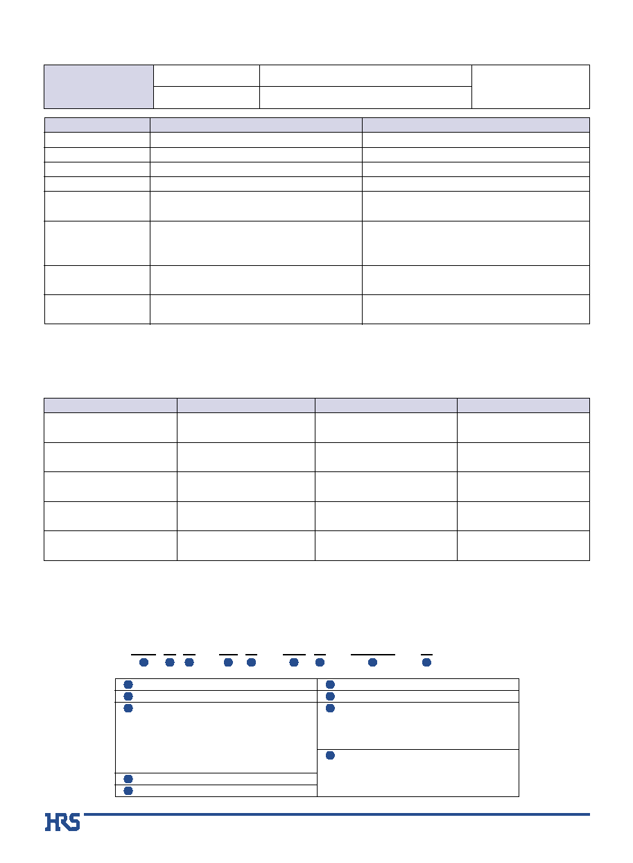
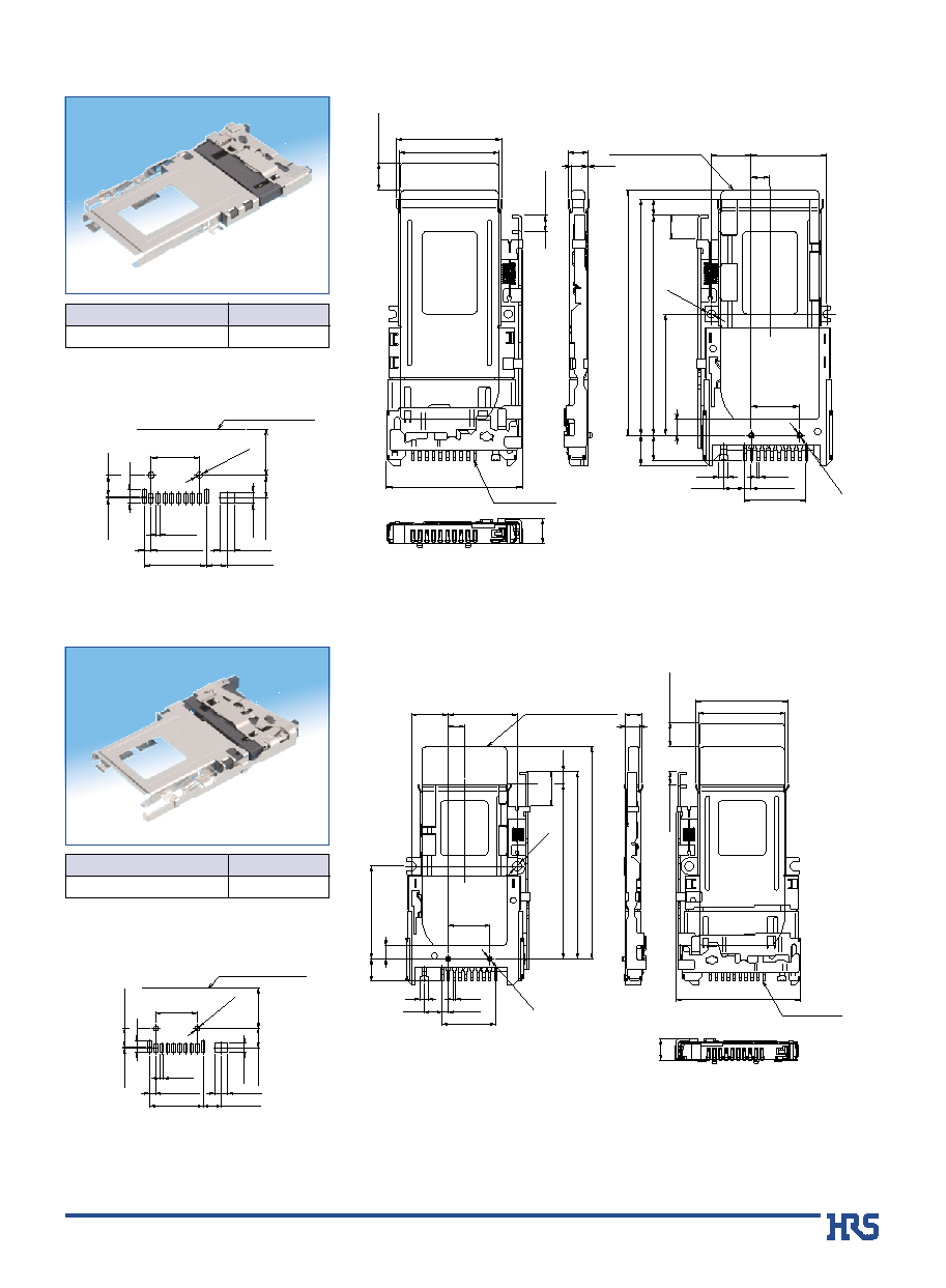
s
Low Profile, Push Insert-Push Eject
33
(31)
29.4
13.5
9.3
26.8
(5.525)
3.2
26.2
(21)
(19.8)
P=1.5
0.6
3.85
3.5
(3.25)
CONTACT No.1
Memory stick card outline
Card ejected
Card fully inserted
Card pushed for ejection
1.9Ī0.1
4Ī0.1
1.9Ī0.1
26.6Ī0.1
9.3Ī0.05
P=1.5Ī0.03
0.9Ī0.05
1.9Ī0.1
26.8Ī0.1
B
PCB mounting pattern
Part No.
CL No.
CB1G-10S-1.5H-PEJC2
CL689-0037-5
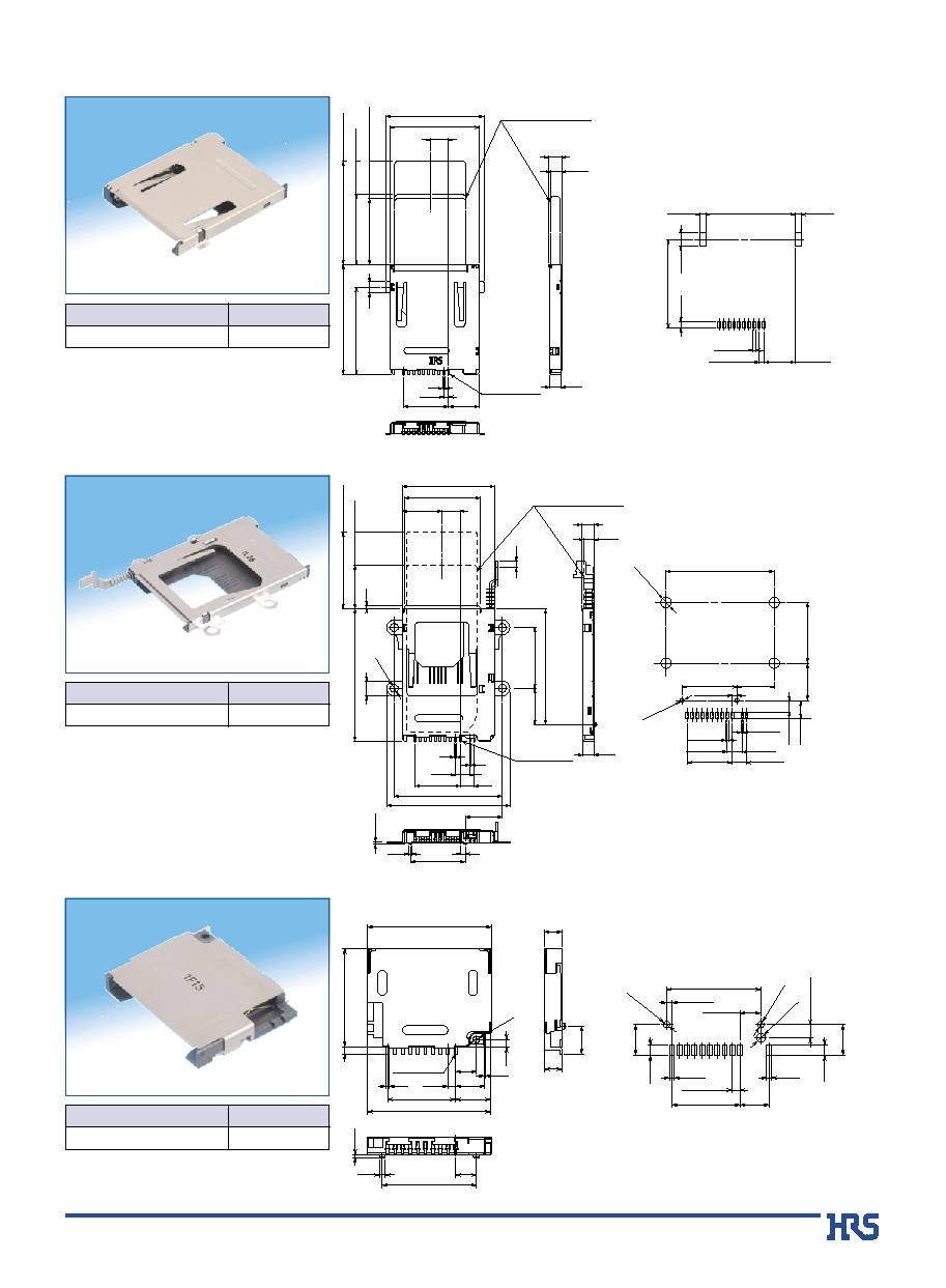
s
Button Touch Eject
27.75
34.9
18.3
37
16.5
32.5
11.15
10.9
22.75
(5.525)
11.975
39.8
(13)
(23)
4.5
(0.8)
13.5
4.2
P=1.5
0.6
0.4
1.5
ō1.2
ō0.55
3
3.85
3.5
(3.25)
(2)
Eject stroke
CONTACT No.1
Memory stick card outline
Card ejected
4-ō2.4
Card fully inserted
32.5Ī00.3
18.3Ī00.3
11.15Ī0.03
16.5Ī0.03
1.5Ī0.03
10.9Ī00.3
3.4Ī0.1
5.3Ī0.1
4.2Ī0.05
13.5Ī0.05
P=1.5Ī0.05
3Ī0.05
0.9Ī0.05
0.6Ī0.05
4-ō3.2
+
0.1
-
0
.0
5
2-ō1.3
+0.05
0
B
PCB mounting pattern
Part No.
CL No.
CB1F-10S-1.5H-TEJL-PA
CL689-0028-4
s
Without Card Ejection
ō1.2
CONTACT No.1
0.3
3.55
24.5
13.5
24.7
6.95
P=1.5
4.15
18.7
0.6
5.8
0.6
4.15
1.45
ō1.3
19.5
1.4
3.5
5.5
ō1.8
+0.1
0
1.05Ī0.05
6.1Ī0.05
P=1.5Ī0.05
13.5Ī0.05
5.8Ī0.05
1Ī0.1
2Ī0.1
2Ī0.1
1Ī0.1
6.1Ī0.05
ō1.3
+0.05
0
ō1.3
+0.05 0
18.7Ī0.03
4.15Ī0.05
2.65Ī0.03
B
PCB mounting pattern
Part No.
CL No.
CB1D-10S-1.5H
CL689-0021-5
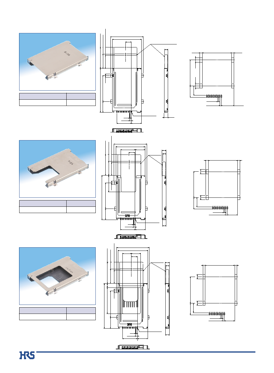
4
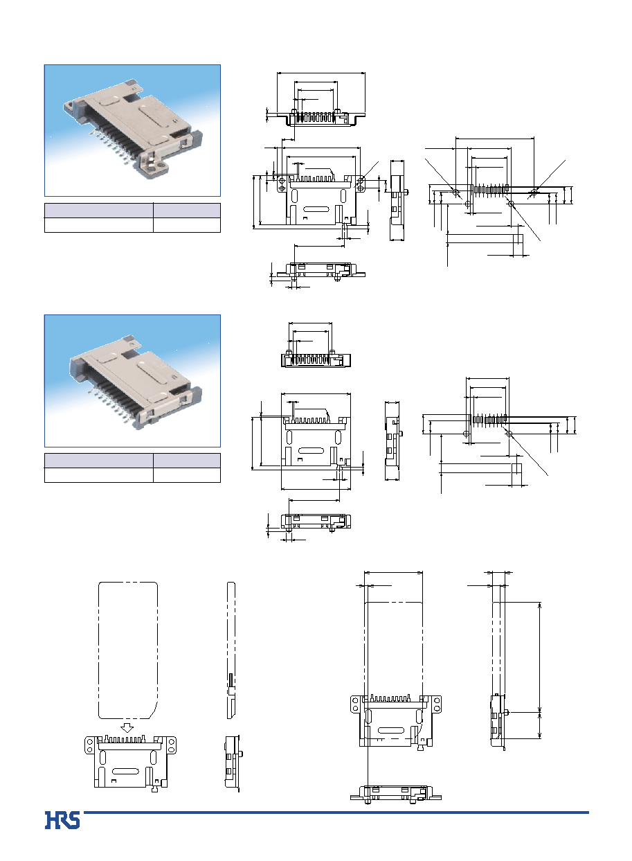
q Normal type
s
Push Insert-Push Eject
(3.25)
Memory stick card outline
(3.5)
24
10.1
3.2
(19.5)
(13.3)
(12)
30.4
26.8
(5.525)
CONTACT No.1
P=1.5
13.5
9.3
0.6
40.8
Card ejected
Card fully inserted
Card pushed for ejection
9.3Ī0.05
P=1.5Ī0.03
0.9Ī0.05
26.8Ī0.1
2.4Ī0.1
2.4Ī0.1
8.6Ī0.1
10.5Ī0.1
24Ī0.03
4Ī0.1
4Ī0.1
B
PCB mounting pattern
Part No.
CL No.
CB1EB-10S-1.5H-PEJC2
CL689-0026-9
q With "U" cut-out
24
10.1
3.2
30.4
CONTACT No.1
P=1.5
13.5
9.3
0.6
(5.525)
26.8
40.8
Memory stick
card outline
13.4
8.85
15.1
3.5
3.85
(3.25)
(19.5)
(13.3)
(12)
Card ejected
Card fully inserted
Card pushed for ejection
4Ī0.1
4Ī0.1
26.8Ī0.1
2.4Ī0.1
2.4Ī0.1
9.3Ī0.05
8.6Ī0.1
10.5Ī0.1
P=1.5Ī0.03
0.9Ī0.05
24Ī0.03
B
PCB mounting pattern
Part No.
CL No.
CB1EBG-10S-1.5H-PEJC2
CL689-0034-7
q With square window
(19.5)
(13.3)
(12)
3.5
3.85
(3.25)
24
10.1
3.2
CONTACT No.1
P=1.5
13.5
9.3
0.6
(5.525)
26.8
40.8
8.3
8.1
3.6
23.8
Memory stick
card outline
29.4
Card ejected
Card fully inserted
Card pushed for ejection
4Ī0.1
4Ī0.1
26.8Ī0.1
1.9Ī0.1
1.9Ī0.1
9.3Ī0.05
8.6Ī0.1
10.5Ī0.1
P=1.5Ī0.03
0.9Ī0.05
24Ī0.03
B
PCB mounting pattern
Part No.
CL No.
CB1EBH-10S-1.5H-PEJC2
CL689-0035-0
5
s
Left Ejection
10.5
23.1
(6)
Card ejected
(3.3)
Eject stroke
21.8
4.45
29.9
5.5
5.55
47.95
51.45
53.45
26.45
8.75
16.45
4.05
P=1.5
0.6
13.5
4.55
2
2-ō1
.2
ō1.8
3.5
5.2
CONTACT No.1
Memory stick card outline
3.65
0.1
6.55
3.45
10.5Ī0.03
P= 1.5Ī0.05
13.5Ī0.05
4.95Ī0.05
2.4Ī0.1
4.65Ī0.05
3Ī0.1
0.4Ī0.05
0.9Ī0.1
3.2Ī0.1
2-ō1.3
+0
.05
0
4.55Ī0.05
48MAX
Front edge of the printed
circuit board
B
PCB mounting pattern
Part No.
CL No.
CB1C-10S-1.5H-EJL(56)
CL689-0006-1-56
s
Right Ejection
(6)
Card ejected
(3.3)
Eject stroke
4.4
23
21.8
5.5
23.4
47.15
17.35
9.25
4.05
P=1.5
0.6
13.5
4.55
2
2-ō1.2
ō2.3
3.2
43.95
8.6
31.2
53.45
10.5
CONTACT No.1
Memory stick card outline
3.65
5.55
3.45
10.5Ī0.03
P=1.5Ī0.05
13.5Ī0.05
4.95Ī0.05
2.4Ī0.1
4.65Ī0.05
3Ī0.1
0.4Ī0.05
0.9Ī0.1
3.2Ī0.1
2-ō1.3
+0.05
0
4.55Ī0.05
41MAX
Front edge of the printed
circuit board
B
PCB mounting pattern
Part No.
CL No.
CB1C-10S-1.5H-EJR(59)
CL689-0007-4-59
6
40.5
4.4
9.5
1.35
21.45
2.8
s
With flange, for screw attachment
4.725Ī0.05
3.8Ī0.1
2.75Ī0.1
2-ō2.1
+0.1
0
ō2.2
+0.2
0
(hole)
30.05Ī0.05
P=1.5Ī0.05
13.5Ī0.05
16.5Ī0.05
6.6Ī0.1
4.9Ī0.1
11.6Ī0.1
3.3Ī0.1
0.9Ī0.05
4.1Ī0.1
ō2.2
+
0.2
0
(hole)
7.4Ī0.1
19.25
1.5
ō2
30.05
18.6
2
1.7
1.2
0.5
2.9
1.9
2-ō1.8
26.3
20.3
4.4
5.25
5.3
0.6
P=1.5
13.5
16.5
33.45
1.5
4.725
4.4Ī0.05
CONTACT No.1
3.8Ī0.1
6.3Ī0.1
(hole)
B
PCB mounting pattern
Part No.
CL No.
CB1A-10S-1.5H(57)
CL689-0001-8-57
s
Without flange
3.8Ī0.1
2.75Ī0.1
2-ō2.1
+
0.1
0
(hole)
P=1.5Ī0.05
13.5Ī0.05
16.5Ī0.05
6.6Ī0.1
4.9Ī0.1
11.6Ī0.1
3.3Ī0.1
0.9Ī0.05
4.1Ī0.1
7.4Ī0.1
19.25
1.5
ō2
2
1.2
26.3
5.25
5.3
0.6
P=1.5
13.5
16.5
18.6
0.5
20.3
26.7
CONTACT No.1
3.8Ī0.1
6.3Ī0.1
B
PCB mounting pattern
B
Memory Stick card insertion direction
B
Memory Stick fully inserted dimensions
Part No.
CL No.
CB1AA-10S-1.5H(57)
CL689-0002-0-57
19Ī0.2
CB1A(1)
P=39.5Ī0.2
330
0
-1
320Ī0.5
21.75Ī0.2
276.5Ī0.3
P=29.5Ī0.2
177Ī0.3
225
0 -1
215Ī0.5
C
C
B
CB1C(R1)
330
0
-1
320Ī0.5
55Ī0.2
27.5Ī0.2
P=40Ī0.2
20PICS
225
0 -1
215Ī0.5
B
160Ī0.3
P=74Ī0.2
222Ī0.3
B
B
330
0
-1
320Ī0.5
225
0 -1
215Ī0.5
177Ī0.3
P=29.5Ī0.2
19Ī0.2
255.5Ī0.3
P=36.5Ī0.2
32.25Ī0.2
CB1E(PEJC1)
2 5 P I C S
P S
A
225
0
-1
215Ī0.5
330
0
-1
320Ī0.5
55Ī0.2
P=55Ī0.2
220Ī0.3
27.5Ī0.2
P=40Ī0.2
160Ī0.3
A
20PICS
PS
CB1F(TEJL1)
225
0
-1
215Ī0.5
330
0
-1
320Ī0.5
P=65Ī0.2
100Ī0.2
195Ī0.3
30.1Ī0.2
P=40Ī0.2
160Ī0.3
A
A
P S
CB1G SERIES
4 0 P I C S
225
0
-1
215Ī0.5
330
0
-1
320Ī0.5
P=36Ī0.2
252Ī0.3
43Ī0.2
30.1Ī0.2
P=40Ī0.2
160Ī0.3
A
A
7
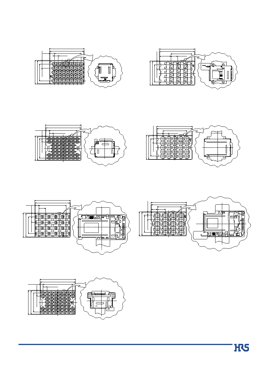
s
Packaging specification (Tray packaging)
q Part Number: CB1G-10S-1.5H-PEJC2(1 tray: 40 pieces)
q Part Number: CB1F-10S-1.5H-TEJL-PA(1 tray: 20 pieces)
q Part Number: CB1D-10S-1.5H(1 tray: 50 pieces)
q Part Number: CB1EB*-10S-1.5H-PEJC2(1 tray: 25 pieces)
q Part Number: CB1C-10S-1.5H-EJL(56)(1 tray: 20 pieces)
q Part Number: CB1C-10S-1.5H-EJR(59)(1 tray: 20 pieces)
q Part Number: CB1A*-10S-1.5H(57)(1 tray: 50 pieces)
A
A
CB1C(L1)
330
0
-1
320Ī0.5
33.4Ī0.2
P=63.3Ī0.2
253.2Ī0.3
29.5Ī0.2
P=52Ī0.2
156Ī0.3
2 0 P I C S
225
0 -1
215Ī0.5
8
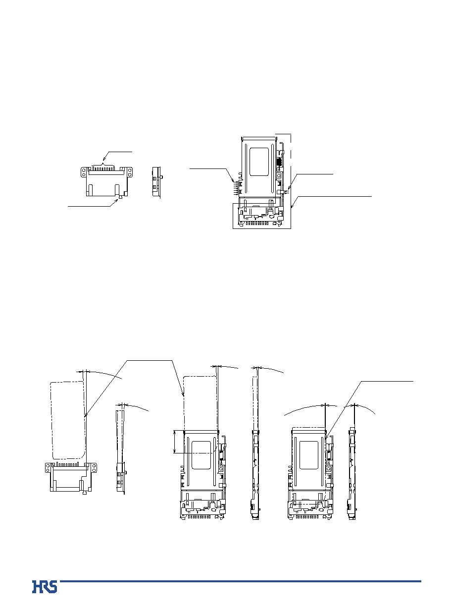
B
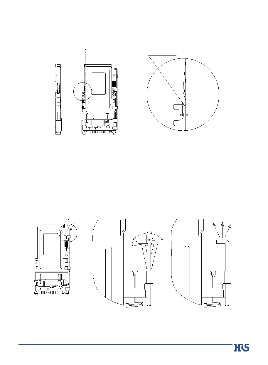
Usage Precautions
1.Care should be taken to correctly insert/withdraw the Memory Stick
ģ
card. Following correct insertion/withdrawal procedures
will prevent device or connector damage.
When handling the CB1C series connectors, hold it in the areas indicated by the arrows, as illustrated below.
2.Follow the recommended insertion angles, as illustrated below.
<Memory Stick Allowable Insertion Angles>
Recommended
holding area
Recommended
holding area
Contacts
Metal hold-down
Contacts, metal hold-down and
ejection components areas
Ī2įMAX
Initial insertion
(15 mm max.)
Complete insertion
(from 15 mm to full insertion)
0įĪ0.22į
15
Ī1įMAX
Ī1įMAX
Ī0.5įMAX
Ī0.2įM
AX
Outline of the Memory
Stick card
Outline of the Memory
Stick card
CB1A Series
CB1A Series
CB1C Series
CB1C Series
9
3.When inserting or withdrawing cards from the CB1C Series, the side contacts on both sides will protrude outward
by 0.6 mm. Care should be taken that they will not be restricted or touch other components.
4. Application of an excessive external force to the push rod may prevent the ejection or insertion of the card.
Do not apply any load in a direction other than the push direction.
(0.6)
side contact
Push direction
Do not twist or bend !
Do not pull !
Push rod
10
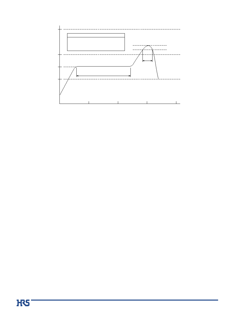
100Á
0Á
150Á
200Á
300Á
50S
0S
100S
150S
200S
240
Á max.
220
Á
Preheating
Soldering
Preheating : 150Á 30 to 90 sec.
IR Reflow Conditions
Soldering : 235Ī5Á 10 sec. max.
220Á min. 10 to 20 sec.
<
Recommended Conditions
>
Reflow system
: IR reflow
Solder
: Paste type 63 Sn/37 Pb (Flux content 9 wt%)
Test board
: Glass epoxy 60mm x 100mm x 1.6 mm
Metal mask thickness
: 0.15 mm
Recommended temperature.
The temperature may be slightly changed according to the solder paste type and volume used.
s
Recommended Temperature Profile